Rotary Encoder
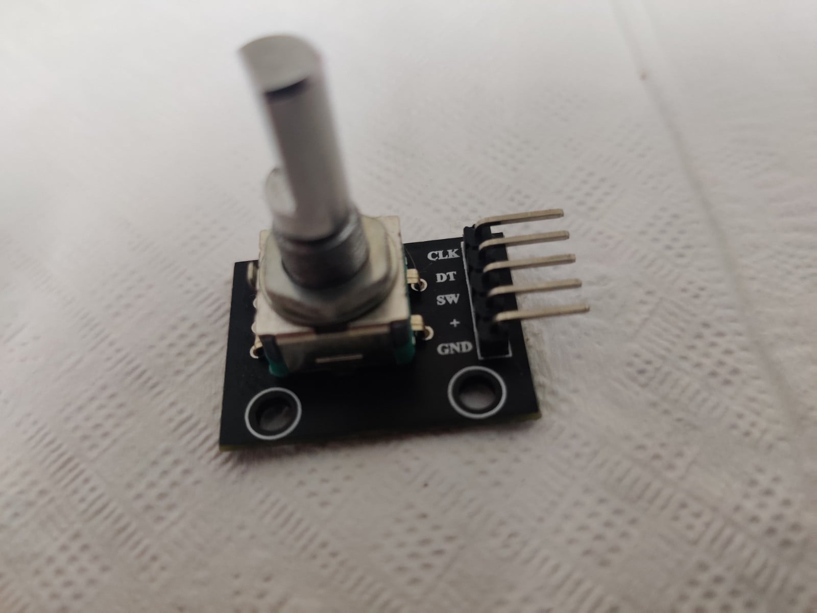
Hi, this blog is a way to keep all my projects in one place, while documenting the process along with all the problems that I encounter.
Rotary encoders are a lot of fun. I have a lot of great memories sitting in front of a music player and turning the knobs all day. The satisfaction of turning a knob is one of the best sensations in the world. In my opinion a dial is the best way to interface certain things like volume or brightness. No button can substitute this satisfaction. I find it a pity that more and more volume controls are being implemented with a up and down buttons rather than a knob. For volume and brightness, it is much more intuitive to use a knob than a button.
So, when it came time for me to implement my own IR remote, I knew I was not going to implement the volume control with buttons but with a knob, this project is part of my IR remote project, you can read other parts of this project here. In this project I would be interfacing a rotary encoder with an Arduino first and then the STM 32 F4 discovery board.
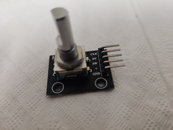
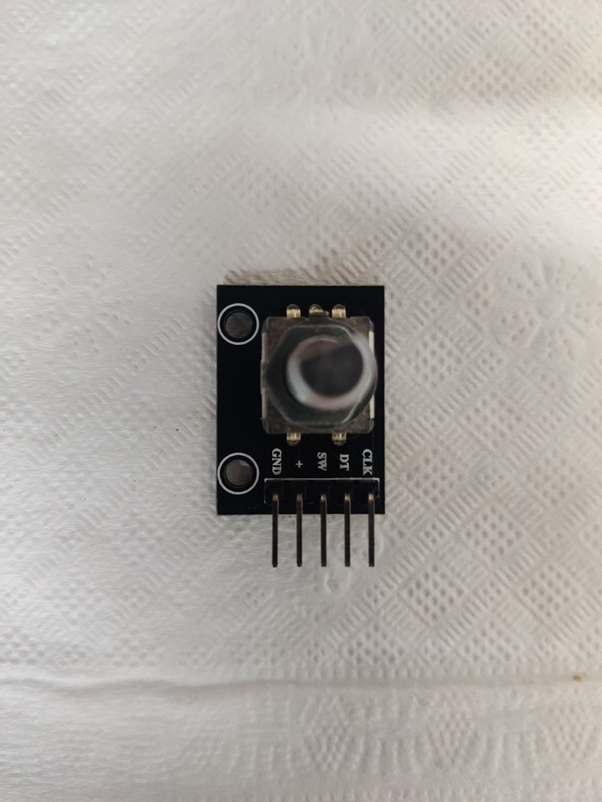
Rotary encoders
What are rotary encoders? How do they work?
Rotary encoders look like potentiometers, the obvious difference is that a rotary encoder is not limited to 180 degrees like a potentiometer. They can be found in many electronic products most commonly used as a volume button, I’m sure you have all encountered one almost on a daily basis. It is crucial to understand how a rotary encoder works in order to write code for it. It consists of two pins a DT and CLK, these two pins are connected to a photodiode, which is placed behind a disk with slots in it. On the other side of the disk is light source as show in the figure
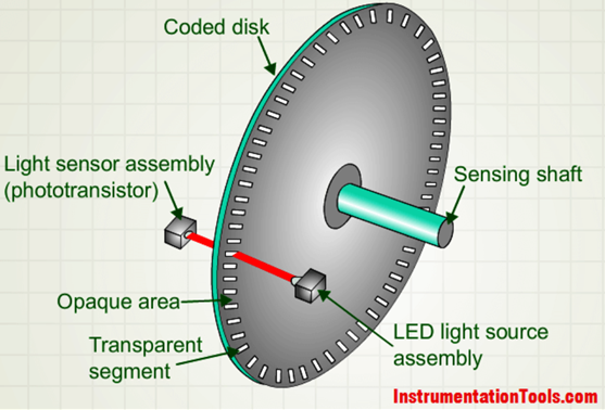
Therefore, if the state of either the DT or CLK pins change we can say that the encoder has been moved. To understand the direction of movement we can see which pin moved first, this can be understood in this picture.
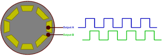
If you haven’t understood the working of a rotary encoder, you can watch the following YouTube videos by DronBot Workshop and how to mechatronics
If you would like to learn more about the different types of rotary encoder you can check out the Wikipedia page
In fact I have implemented a rotary encoder using a BLDC motor which you can read here
Arduino Implementation
First, we are going to implement a basic counter using a rotary encoder using an Arduino, this project will give us an idea to work with a rotary encoder. I would turn the encoder clock wise to increase the volume and turn it anti clockwise to decrease the volume and display the volume on the serial monitor.
Hardware
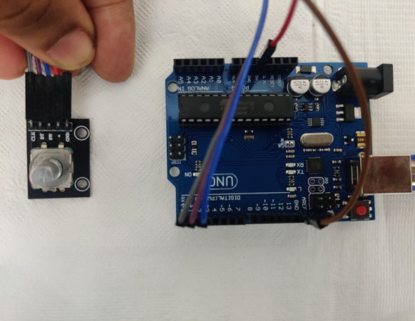
All I need to do is to connect the Arduino to the rotary encoder. I used male to female connecters to do this. There is no reason I choose these pins you can use any other pin and change it in the code. Connect:
“+” pin to “+5v” pin of the Arduino.
“GND” pin to ground pin of the Arduino.
“DT” to digital pin 1 and “CLK” to digital pin 0.
Code
#define DT 1                //connect DT to digital pin 1
#define CLK 0               //connect CLK to digital pin 0

int vol=50;                 //variable for volume

int currentCLK;             //variables for rotary encoder
int lastCLK;                //variables for rotary encoder
int currentDT;

void setup() {
  Serial.begin(9600);       //to start serial monitor
  pinMode(DT,INPUT);        //setting pin as input
  pinMode(CLK,INPUT);       //setting pin as input
  lastCLK = digitalRead(CLK);                   //setting last state of CLK pin
}

void loop() {
    currentCLK = digitalRead(CLK);              //get the current state of of CLK pin
    if (currentCLK != lastCLK){                 //if the curent state is not the same as the preivious state it indicates movement
      currentDT=digitalRead(DT);
      if (currentDT != currentCLK){             //once there is movement we check the other pin to see if it is clockwise of anticlockwise
        vol = vol - 1;                          //if anticlockwise we decerement the index
        }
      else{                                     //if clockwise we increment the index
        vol = vol + 1;
        }
    Serial.println(vol);                       //display volume
    lastCLK = currentCLK;                      //update last value of CLK
    }
}
Output
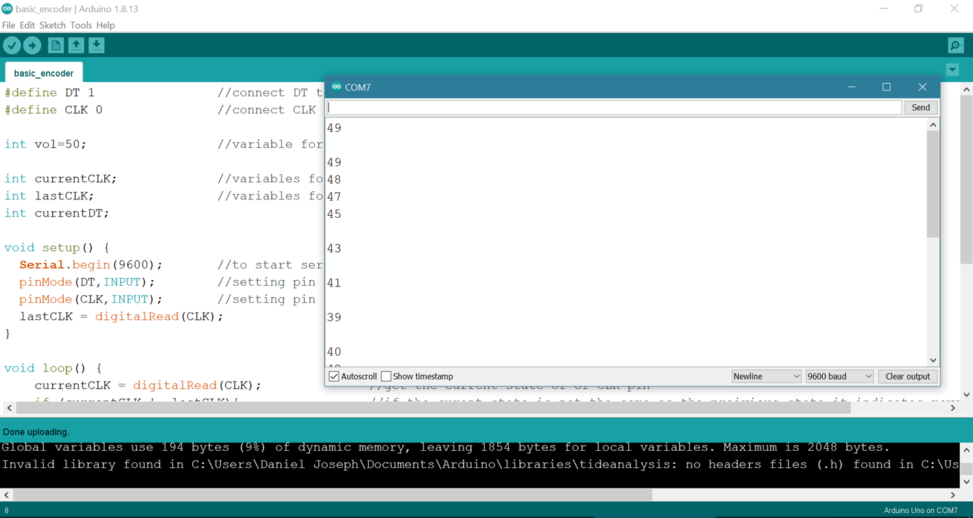
The code works pretty well, however the serial monitor doesn’t work to well, this is because our serial connection is too slow compared to the speed of the rotary encoder. The rotary encoder is actually very fast this causes the volume to increment by two steps instead of one at times. Anyway, now I feel we got a good understanding of how to code the rotary encoder, so we can move on to interfacing it with the STM 32.
STM 32 F4 Implementation.
Push button
I haven’t done many projects with the STM 32 F4 discovery board that uses input and the IDR register, so first I would like to implement a simple pushbutton code that will light up all four LED’s when the button of the rotary encoder is pushed.
I connected the SW pin of the rotary encoder to port E pin 0. Important thing to note is that push button is normally HIGH and when the button is pressed a low signal is send, or in other words, it is a low enable signal.
#include "stm32f4xx.h"

void configureLED(void);
void configurePB(void);
void msDelay(uint32_t msTime);
int main(void)
{
    configureLED();
    configurePB();
    unsigned int PB_state=0;
    msDelay(500);
    while(1)
    {
        PB_state=((GPIOE->IDR) & (0x1UL<<0));
        if(PB_state==(0x1UL<<0))
        {
            GPIOD->ODR = 0x0UL;
        }
        else
        {
            GPIOD->ODR = (0xFUL<<12);
            msDelay(100);
        }
    }
}
void configureLED(void)
{
    RCC->AHB1ENR |=(1UL<<3);
    GPIOD->MODER &= ~(0xFFUL<<12*2);
    GPIOD->MODER |= (0x55UL<<12*2);
}

void configurePB(void)
{
    RCC->AHB1ENR |=(0x1UL<<4);
}

void msDelay(uint32_t msTime)
{
    //"For loop" takes 4 clock cycles to get executed. Clock frequency is 16MHz
    //16MHz/4=4MHz. If we want 1000ms delay, 4MHz/1000=4000, so we have to multiply by 4000 to get a delay of 1s
    for(uint32_t i=0;i<(msTime*4000);i++);
}
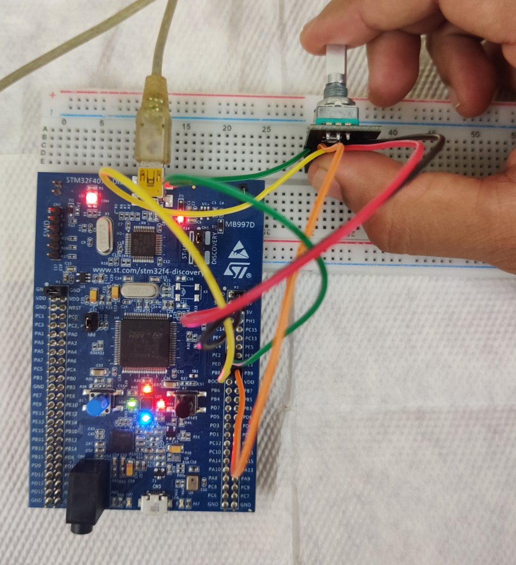
This code works well and every time we press the button all four LED’s turn on and stays on for 100 micro seconds. Now we can go on to implement a simple clockwise and anticlockwise implementation.
Direction of Rotation
In this code we will turn on the green LED if the rotary encoder is turned clockwise and the red LED if the encoder is turned anticlockwise. To write this code I just take the push button code along with the rotary encoder code for Arduino and converted into register level code on keil
#include "stm32f4xx.h"
void configureLED(void);
void configurePB(void);
void msDelay(uint32_t msTime);
int main(void)
{
    configureLED();
    configurePB();
    unsigned int currentCLK=0;
    unsigned int lastCLK=0;
    unsigned int currentDT=0;
    lastCLK = ((GPIOE->IDR) & (0x1UL<<2));
    msDelay(500);
    while(1)
    {
        currentCLK = ((GPIOE->IDR) & (0x1UL<<2));
        if (currentCLK != lastCLK){
            currentDT = ((GPIOE->IDR) & (0x1UL<<1));
            if (currentDT != currentCLK) {
                GPIOD->ODR = (0xCUL<<12);
                msDelay(100);}

            else {
                GPIOD->ODR = (0x3UL<<12);
            msDelay(100);}
        }
        currentCLK=lastCLK;
    }
}
void configureLED(void)
{
    RCC->AHB1ENR |=(1UL<<3);
    GPIOD->MODER &= ~(0xFFUL<<12*2);
    GPIOD->MODER |= (0x55UL<<12*2);
}

void configurePB(void)
{
    RCC->AHB1ENR |=(0x1UL<<4);
}

void msDelay(uint32_t msTime)
{
    //"For loop" takes 4 clock cycles to get executed. Clock frequency is 16MHz
    //16MHz/4=4MHz. If we want 1000ms delay, 4MHz/1000=4000, so we have to multiply by 4000 to get a delay of 1s
    for(uint32_t i=0;i<msTime*4000;i++);
}
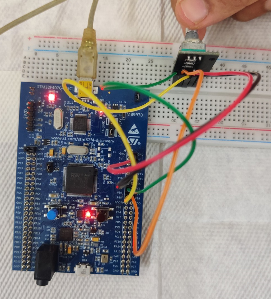
This also seems to work perfectly, there isn’t any problems like that we faced on the Arduino this is because the clock speed and function speed are much faster on the STM 32. Now we can implement a volume control.
Volume control
There is a small problem implementing a volume control as I don’t have a serial monitor on keil, I can implement a volume control but I would not be able to display the volume. So, I developed a smart but complicated way to test if the code works properly. So initially I set the volume at 50 and when I turn it clockwise the red LED turns on and the volume increases, when I turn it anticlockwise the green LED turns on and the volume decreases. Now every time the volume is at 50 the other 2 LED turn on. Every time the mute button is pressed all four LED turn on until it is pressed again or the knob is turned.
#include "stm32f4xx.h"
void configureLED(void);
void configurePB(void);
void msDelay(uint32_t msTime);
int main(void)
{
    configureLED();
    configurePB();
    unsigned int currentCLK=0;
    unsigned int lastCLK=0;
    unsigned int currentDT=0;
    unsigned int state=50;
    unsigned int butt=1;
    lastCLK = ((GPIOE->IDR) & (0x1UL<<2));
    msDelay(100);
    while(1)
    {
        currentCLK = ((GPIOE->IDR) & (0x1UL<<2));
        if (currentCLK != lastCLK){
            currentDT = ((GPIOE->IDR) & (0x1UL<<1));
            if (currentDT != currentCLK) {
                GPIOD->ODR = (0x1UL<<12);
                msDelay(100);
                state=state+1;
            }
            else {
                GPIOD->ODR = (0x4UL<<12);
                msDelay(100);
                state=state-1;
            }
        }
        currentCLK=lastCLK;
        butt=((GPIOE->IDR) & (0x1UL<<0));
        if (butt !=0x1UL){

            GPIOD->ODR = (0xFUL<<12);
            msDelay(100);
        }
        if(state==50){
            GPIOD->ODR = (0xAUL<<12);
            msDelay(100);}
    }
}
void configureLED(void)
{
    RCC->AHB1ENR |=(1UL<<3);
    GPIOD->MODER &= ~(0xFFUL<<12*2);
    GPIOD->MODER |= (0x55UL<<12*2);
}

void configurePB(void)
{
    RCC->AHB1ENR |=(0x1UL<<4);
}

void msDelay(uint32_t msTime)
{
    //"For loop" takes 4 clock cycles to get executed. Clock frequency is 16MHz
    //16MHz/4=4MHz. If we want 1000ms delay, 4MHz/1000=4000, so we have to multiply by 4000 to get a delay of 1s
    for(uint32_t i=0;i<msTime*4000;i++);
}
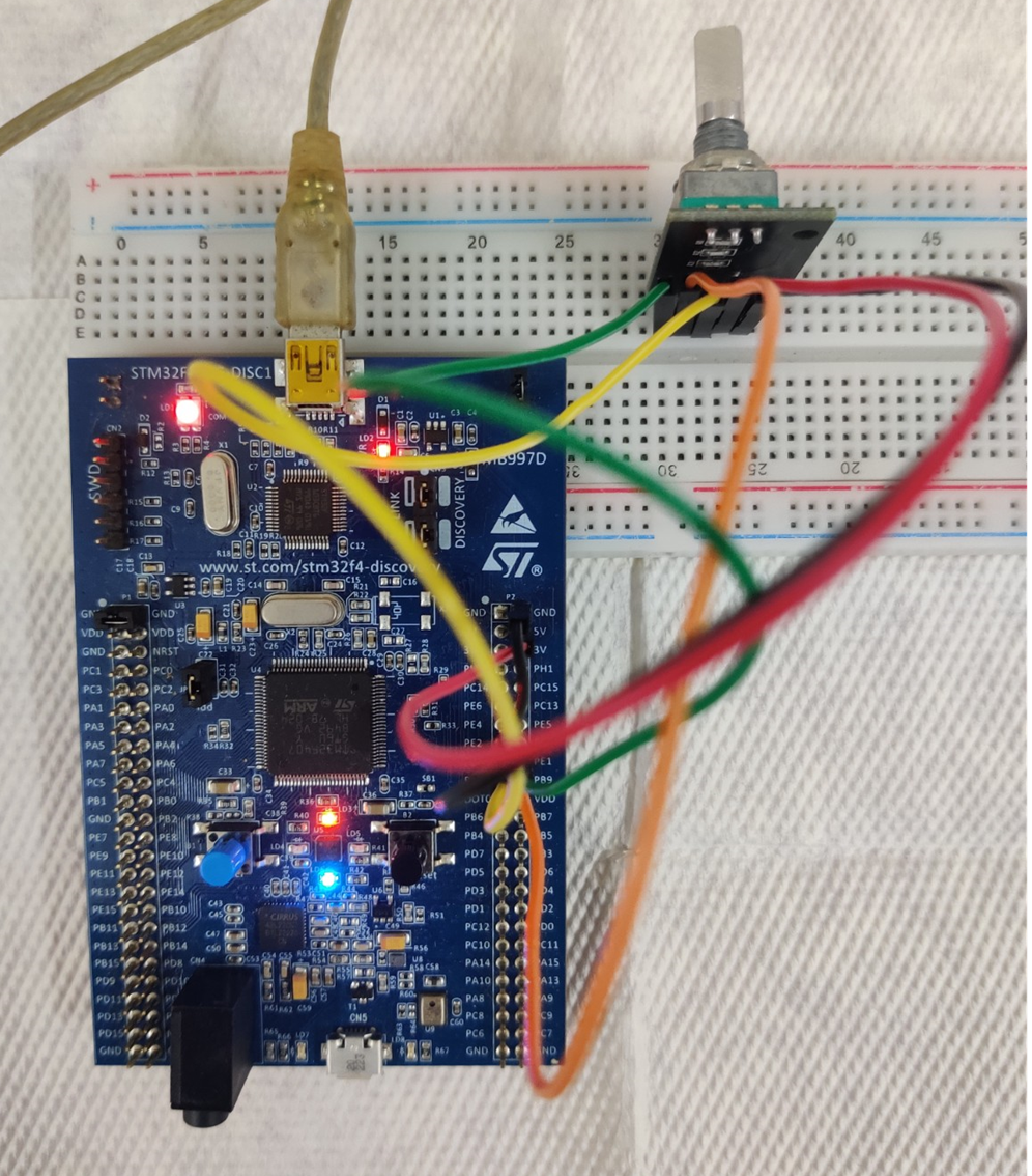
Now we have succefully interfaced a rotary encoder with the STM32 F4 discovery board.
Code Explanation
#include "stm32f4xx.h"
void configureLED(void);
void configurePB(void);
void msDelay(uint32_t msTime);
int main(void)
{
    configureLED();
    configurePB();
    unsigned int currentCLK=0;
    unsigned int lastCLK=0;
    unsigned int currentDT=0;
    unsigned int state=50;
    unsigned int butt=1;

    lastCLK = ((GPIOE->IDR) & (0x1UL<<2));
    msDelay(100);
The first four lines are initializing functions which we will define after the main code. The main code starts by configuring the LED's which are connected to port D and then the encoder pins which are connected to port E. We then write five lines to initialize few variables which we would use later. The second last line is similar to a digitalRead in an Arduino we the IDR register contains the value of all the GPIO pins in port E, we use the and function to get the value of the 3rd bit. This corresponds to the value of pin 3, which is connected to the CLK pin.
while(1)
    {
        currentCLK = ((GPIOE->IDR) & (0x1UL<<2));
        if (currentCLK != lastCLK){
            currentDT = ((GPIOE->IDR) & (0x1UL<<1));
            if (currentDT != currentCLK) {
                GPIOD->ODR = (0x1UL<<12);
                msDelay(100);
                state=state+1;
            }
            else {
                GPIOD->ODR = (0x4UL<<12);
                msDelay(100);
                state=state-1;
            }
        }
This section is very similar to the Arduino code, so if you can understand the Arduino code then this is quite easy. IF the current state of the CLK pin is different from the previous state of the CLK pin, it means that there is some movement. once we know that there is movement, we read the value of the DT pin to see if the direction of rotation is clockwise or anticlockwise. If it is clockwise, we increment the "state" variable and turn on the green LED and wait for 100 micro seconds. If it is anticlockwise, we decrement the "state" variable and turn on the red LED.
void configureLED(void)
{
    RCC->AHB1ENR |=(1UL<<3);
    GPIOD->MODER &= ~(0xFFUL<<12*2);
    GPIOD->MODER |= (0x55UL<<12*2);
}

void configurePB(void)
{
    RCC->AHB1ENR |=(0x1UL<<4);
}

void msDelay(uint32_t msTime)
{
    //"For loop" takes 4 clock cycles to get executed. Clock frequency is 16MHz
    //16MHz/4=4MHz. If we want 1000ms delay, 4MHz/1000=4000, so we have to multiply by 4000 to get a delay of 1s
    for(uint32_t i=0;i<msTime*4000;i++);
}
These are the function decelerations the first function configures the 4 LED connected to port D pin 12, 13, 14, 15 as output as well as enables the clock for this port. The second function enables the clock for port E, we do not need to declare these pins as input as all pins are configured as input by default. The last function is the generic code we write for a software delay.


