

So the other day while I was scrolling through my YouTube I came across a video by great Scott, where he took apart an old HDD (hard disk drive) and with help from an Arduino, converted it into a rotary encoder.
Rotary encoders are the knobs which are most commonly found in volume knobs, and are very useful in projects. The hard disk looks better than a standard rotary encoder and is much more satisfying to use. After seeing him do it, I thought to myself, "Hmmm... seems interesting and not too hard, I could try it out."
So, the first thing I need a hard drive, well a corrupted or not working hard drive really, cause I’m not going to waste a hard drive just as a rotary encoder. Luckily, I spend most of lockdown gathering electronic waste and so I was in possession of an old hard drive that was used in a CCTV system, but had stopped working due to a faulty reading head. All I’m going to use is the BLDC motor (Brushless Direct current motors), which seemed to work fine.
Getting Started
The first step was to take apart the hard disk and examine the internals. This wasn’t too hard, just taking apart some regular Torx screws. They were however, extremely tight, as the hard drive is a very sensitive device and any dust would kill it instantly.
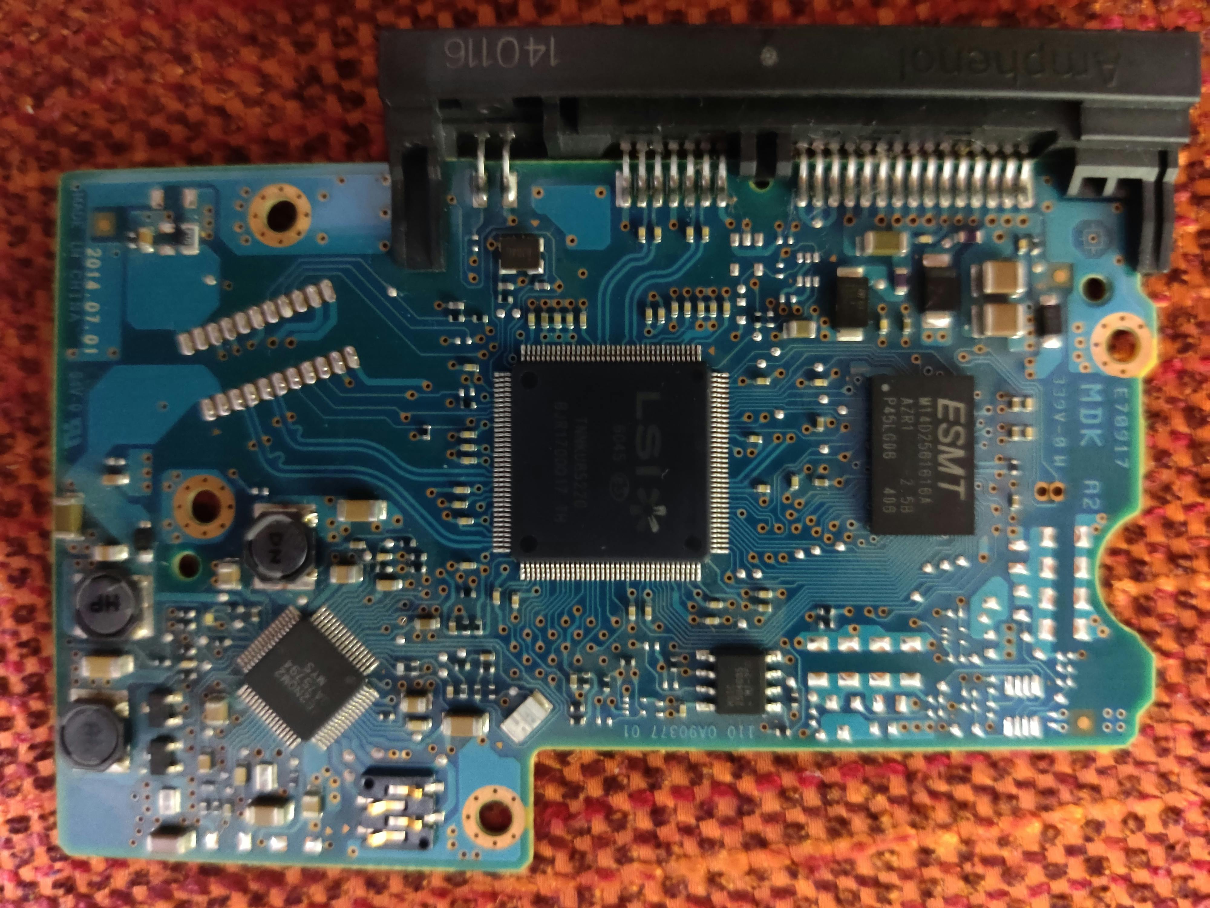
 The back of the drive had a PCB with a microcontroller, this is the management systems of the disk. At the end of this project, we shall take a closer look at this PCB and try to reverse engineer it.
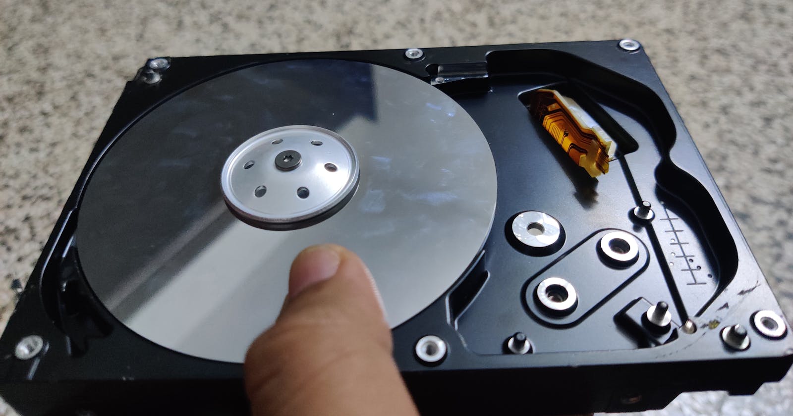
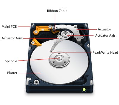
 Now when we open up the top cover, we see the platters (which is what the data is stored on), the head (what writes the data) and the magnets (that control the head). More about it here.
 I first take apart these strong neodymium magnets which are a lot of fun, and are quite neat, definitely want to save that for latter. Next, we take apart the head, if we were doing data recovery or planned on using them again, we wouldn't just take it apart, but as our head is already damaged, we can afford to be unwary with it. If you are interested in how they deal with hard drives to recover data then I remember seeing a Louis Rossmann video which was pretty cool: Heads Swap, Platter Swap
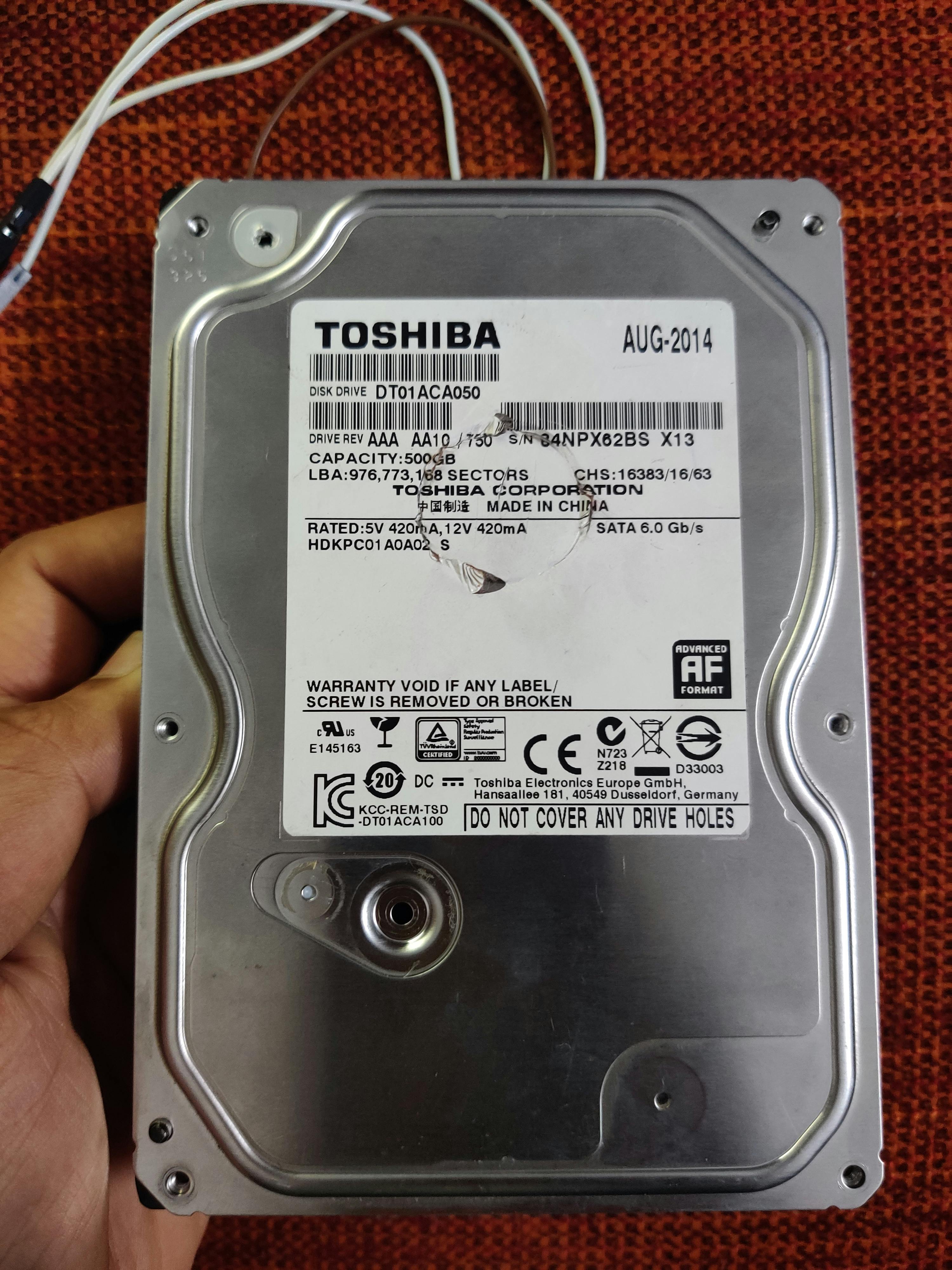
Okay so now we are got all the stuff out, we are left with just the platter, we could take the platter apart to see the BLCD motor, but we don’t really need to cause there are contacts on the back of the drive which are connected to the BLDC motor.
I first take apart these strong neodymium magnets which are a lot of fun, and are quite neat, definitely want to save that for latter. Next, we take apart the head, if we were doing data recovery or planned on using them again, we wouldn't just take it apart, but as our head is already damaged, we can afford to be unwary with it. If you are interested in how they deal with hard drives to recover data then I remember seeing a Louis Rossmann video which was pretty cool: Heads Swap, Platter Swap
Okay so now we are got all the stuff out, we are left with just the platter, we could take the platter apart to see the BLCD motor, but we don’t really need to cause there are contacts on the back of the drive which are connected to the BLDC motor.
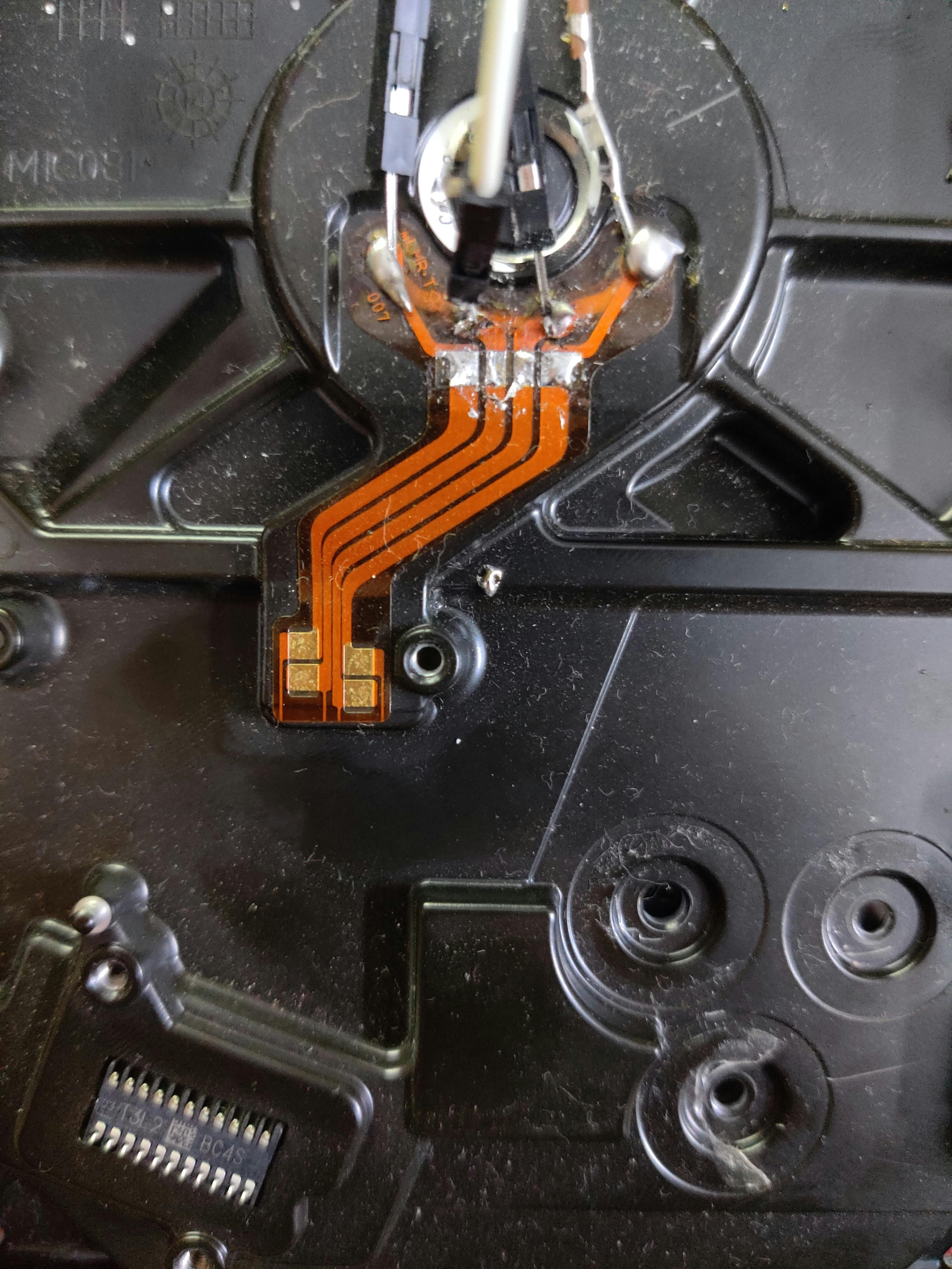 Now we get to the main part, we have to figure out what kind of BLDC motor we have, it could be star or delta connected. We can easily figure this out by the number of connections, mine is clearly star connected as it has 4 connections: the 3 phases and the common neutral. There are some models which use the delta connected one, which I cannot really provide much information about as I haven’t come across it but I did find one video here.
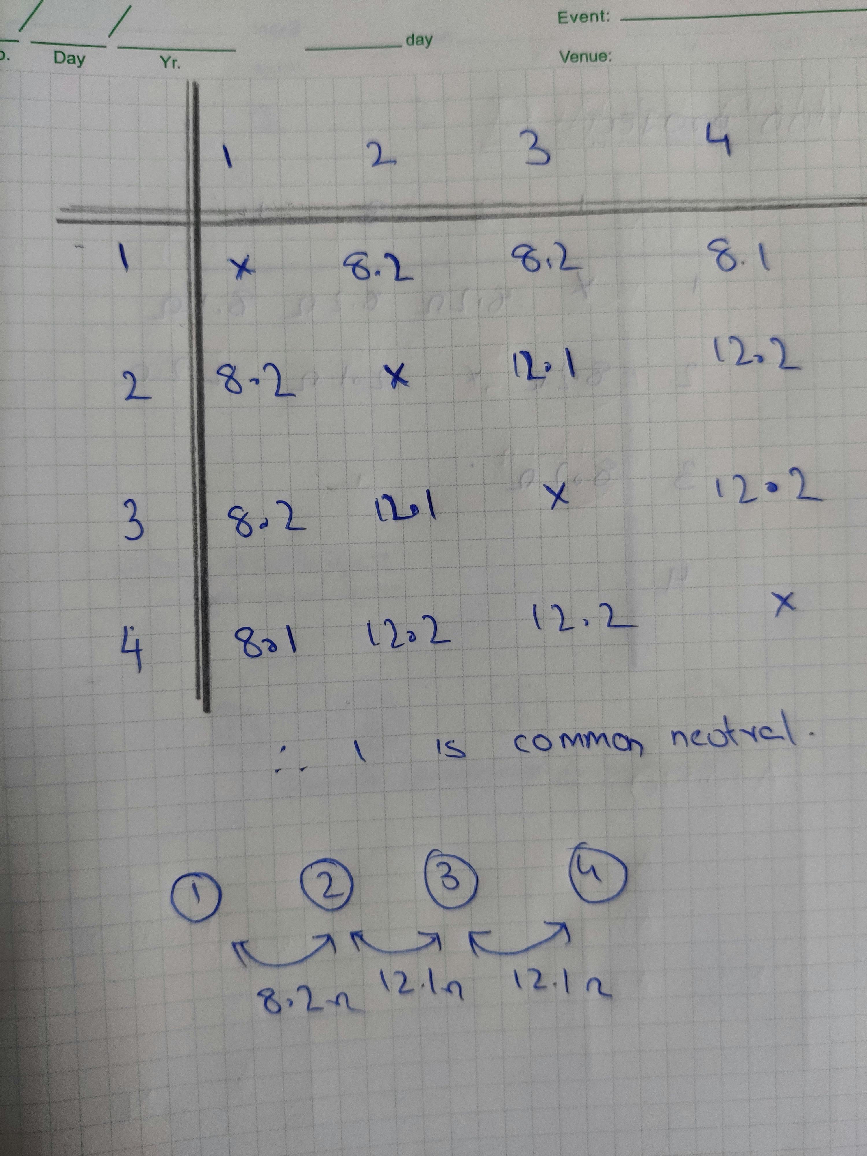
Now after figuring out the type of connection, we need to figure which connection is which, essentially, which is neutral. We do that by measuring resistance. Now in theory it sounds simple, but actually it’s a lot harder. The first problem is that the resistances are very small (less than 20 ohms), which means you would ideally want to have an accurate multimeter with the capability to read very small values, however I have a cheap multimeter, but luckily it would do as you aren’t looking to get proper readings but just trying to find the one neutral. The next big problem was as we are dealing with such small resistances, surface resistance comes into picture, it took me forever to realise this. So, to deal with the surface resistance the first thing you to make sure is that your skin is not in contact, you can’t just hold the wires and probes between your fingers like you normally do.
It is also essential to use the same set of contacts with minimal amount of dirt or corrosion on it. If you keep these points in mind, it wouldn’t be too hard to find out which is the neutral. I found that the resistance between the phases was 12.1 ohms and the resistance between the phase a neutral was 8.2 ohms.
Now we get to the main part, we have to figure out what kind of BLDC motor we have, it could be star or delta connected. We can easily figure this out by the number of connections, mine is clearly star connected as it has 4 connections: the 3 phases and the common neutral. There are some models which use the delta connected one, which I cannot really provide much information about as I haven’t come across it but I did find one video here.
Now after figuring out the type of connection, we need to figure which connection is which, essentially, which is neutral. We do that by measuring resistance. Now in theory it sounds simple, but actually it’s a lot harder. The first problem is that the resistances are very small (less than 20 ohms), which means you would ideally want to have an accurate multimeter with the capability to read very small values, however I have a cheap multimeter, but luckily it would do as you aren’t looking to get proper readings but just trying to find the one neutral. The next big problem was as we are dealing with such small resistances, surface resistance comes into picture, it took me forever to realise this. So, to deal with the surface resistance the first thing you to make sure is that your skin is not in contact, you can’t just hold the wires and probes between your fingers like you normally do.
It is also essential to use the same set of contacts with minimal amount of dirt or corrosion on it. If you keep these points in mind, it wouldn’t be too hard to find out which is the neutral. I found that the resistance between the phases was 12.1 ohms and the resistance between the phase a neutral was 8.2 ohms.
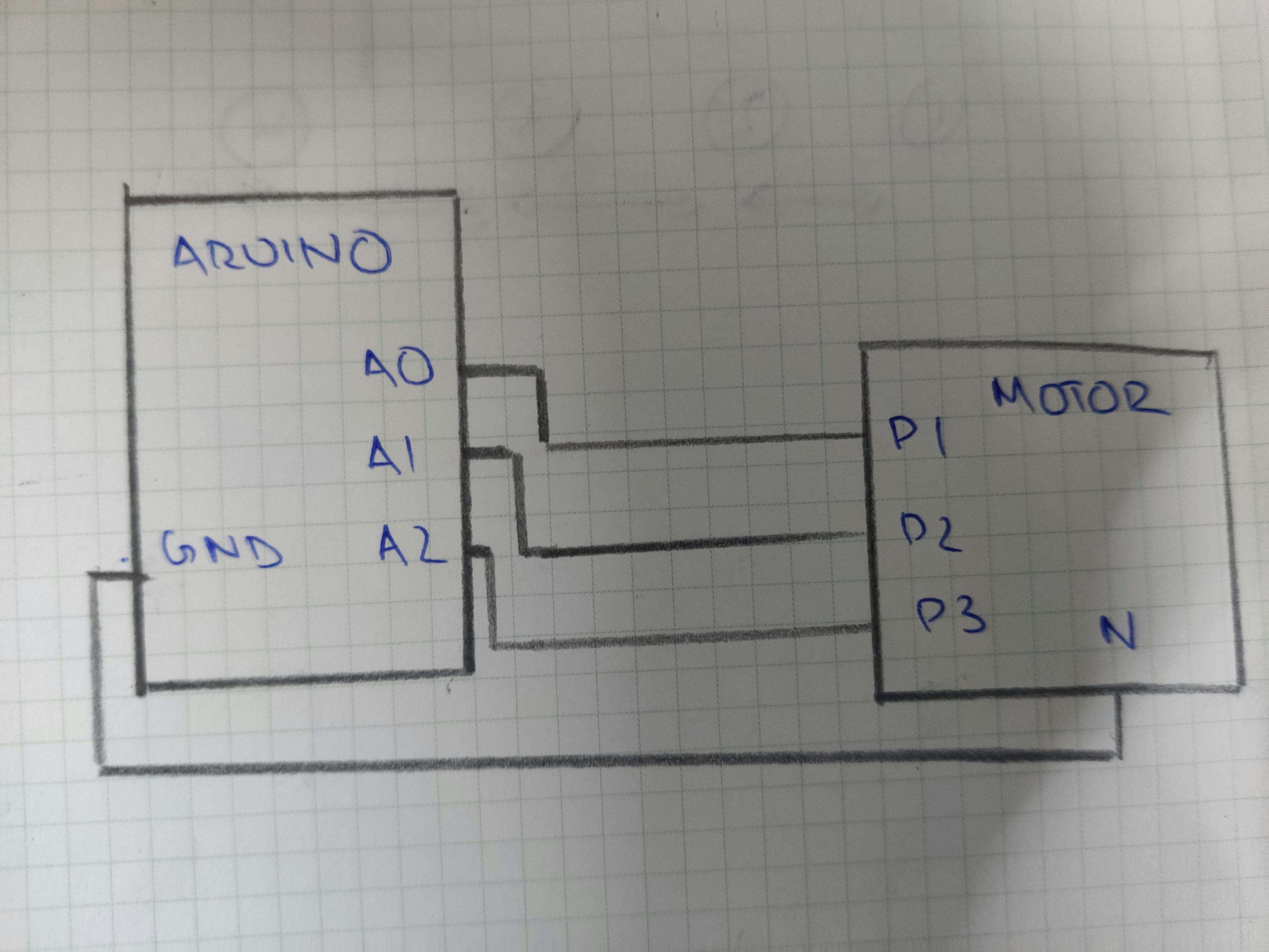
 Now it’s time to solder some wires to the contacts to connect them to the Arduino, this step shouldn’t be hard if you know to solder, however I don’t have much experience with soldering and I only had a 75W soldering iron, which was way too hot, but luckily, I managed to get the job done. Once we have the wires it’s time to bring in our Arduino, I’m using a regular Arduino uno clone, you may use whatever is available. We just connect the neural to the ground pin of the Arduino and the 3 phases of the motor to the first 3 analog read pins. The connection is very simple, according to the following diagram.
Working Principle
So well now that we have everything set up let’s look how this is supposed to work. All a rotary encoder needs to do is figure out how fast it is rotating and the direction in which its turning. A BLDC motor, rotates when a 3-phase ac supply is applied to it, however if no supply it applied, and the motor is manually rotated, it produces a very small 3 phase ac voltage. This voltage is too small to do anything, but luckily its substantial enough to be read by the Arduino. Ideally what I would do is hook up the phases of the motor to the oscilloscope and rotate the motor to observe the waveform, however I do not own an oscilloscope, great Scott does show the waveform in his video. The way we know the direction of rotation, is in the order of the waveform. For example, it may be A1, A2, A3 when rotated clockwise and A2, A1, A3 when rotated anticlockwise. A BLDC motor works with the principle of alternating stator windings. find out more here
Code
What we need is first the analog digital converter (ADC) in the Arduino to read the values from the motor, now this is actually the hardest part for me. I don’t know how the ADC code part is actually, I don’t have any experience with the ADC of the Arduino so I am mostly referring great Scott’s code, which he has provide on his patreon.
#define L1 A0     //initiallising the A0 analog port with variable L1
#define L2 A1     //initiallising the A1 analog port with variable L2
#define L3 A2    //initiallising the A2 analog port with variable L3
boolean L1Val = 0;
const unsigned char PS_128 = (1 << ADPS2) | (1 << ADPS1) | (1 << ADPS0);

void setup() {
  ADCSRA &= ~PS_128;   //setting up adc
  ADCSRA |= (1 << ADPS1) | (1 << ADPS0);
  Serial.begin(9600);  //setting up baud rate of serial monitor
  analogReference(INTERNAL);  //using the internal ADC
  pinMode(L1, INPUT);   //setting up L1 as input
  pinMode(L2, INPUT);  //setting up L2 as input
  pinMode(L3, INPUT);  //setting up L3 as input

}

void loop() {
  if ((analogRead(L1) > 200) && (L1Val == 0)) { //geting values for L1 phase
    L1Val = 1;
  }

  if ((L1Val == 1) && (analogRead(L2) > 200)) { //comparing L1
    Serial.println("clockwise");
    L1Val = 0;
    delay(500);
  }

  if ((L1Val == 1) && (analogRead(L3) > 200)) {
    Serial.println("anticlockwise");
    L1Val = 0;
    delay(500);
  }
}
This code only tells us if we are rotating it clockwise or anticlockwise, that is only the direction of rotation, what I had to do since I did not have an oscilloscope was to see which phase came first, this involved changing the initial definition until it worked.
#define L1 A1
#define L2 A2
#define L3 A0
I tried all 6 different combinations until I found which worked for me. Had I had an oscilloscope it would have been a lot easier, but hey, this is engineering. Now that I see that the code works very well after testing it, it’s time for some more useful applications.
#define L1 A0
#define L2 A1
#define L3 A2
int lcdval = 100;
boolean L1Val = 0;
const unsigned char PS_128 = (1 << ADPS2) | (1 << ADPS1) | (1 << ADPS0);


void setup() {
  Serial.begin(9600);
  ADCSRA &= ~PS_128;
  ADCSRA |= (1 << ADPS1) | (1 << ADPS0);
  analogReference(INTERNAL);
  pinMode(L1, INPUT);
  pinMode(L2, INPUT);
  pinMode(L3, INPUT);
  Serial.print(lcdval);


}

void loop() {
  if ((analogRead(L1) > 200) && (L1Val == 0)) {
    L1Val = 1;
  }

  if ((L1Val == 1) && (analogRead(L2) > 200)) {
    lcdval = lcdval + 1;
   // Serial.clear();
    Serial.println(lcdval);
    L1Val = 0;
    delay(100);

  }

  if ((L1Val == 1) && (analogRead(L3) > 200)) {
    lcdval = lcdval - 1;
    //Serial.clear();
    Serial.println(lcdval);
    L1Val = 0;
    delay(100);
  }
}
This is very similar to the previous code, it’s just that here we increment or decrement from a set value of 100. This works but just about, I found many random issues with it. It works most of the time, but occasionally it reduces too much and sometimes it moves to fast, I found it works best if you rotate it half a revolution fast and stop it and rotate another revolution, rather than continuous rotation. This issue can actually be seen in the code, and with more creative code can improve it. However we actually might still be struggling with limitation of the Arduino and its 8 bit resolution ADC, we could try this with an external ADC or another microcontroller with a hight resolution, but despite a more creative code and a better ADC we would still not be very precise due to the technology. A standard rotary encoder will always be more precise, and more sensitive that this work around. It is all down to the fundamental technology behind it, this clearly isn’t the use of a BLDC motor. That however does not render this project useless, rotating a HDD is a lot more satisfying that a regular rotary encode, and it could be used for low precision tasks, like volume or brightness control. It can also be used for dimming or controlling the intensity of a light. I did find a video of an application on YouTube: LED circle, LED interface, MOUSE (I cannot be sure if the mouse is real, but in concept it is sound)
PCB analysis
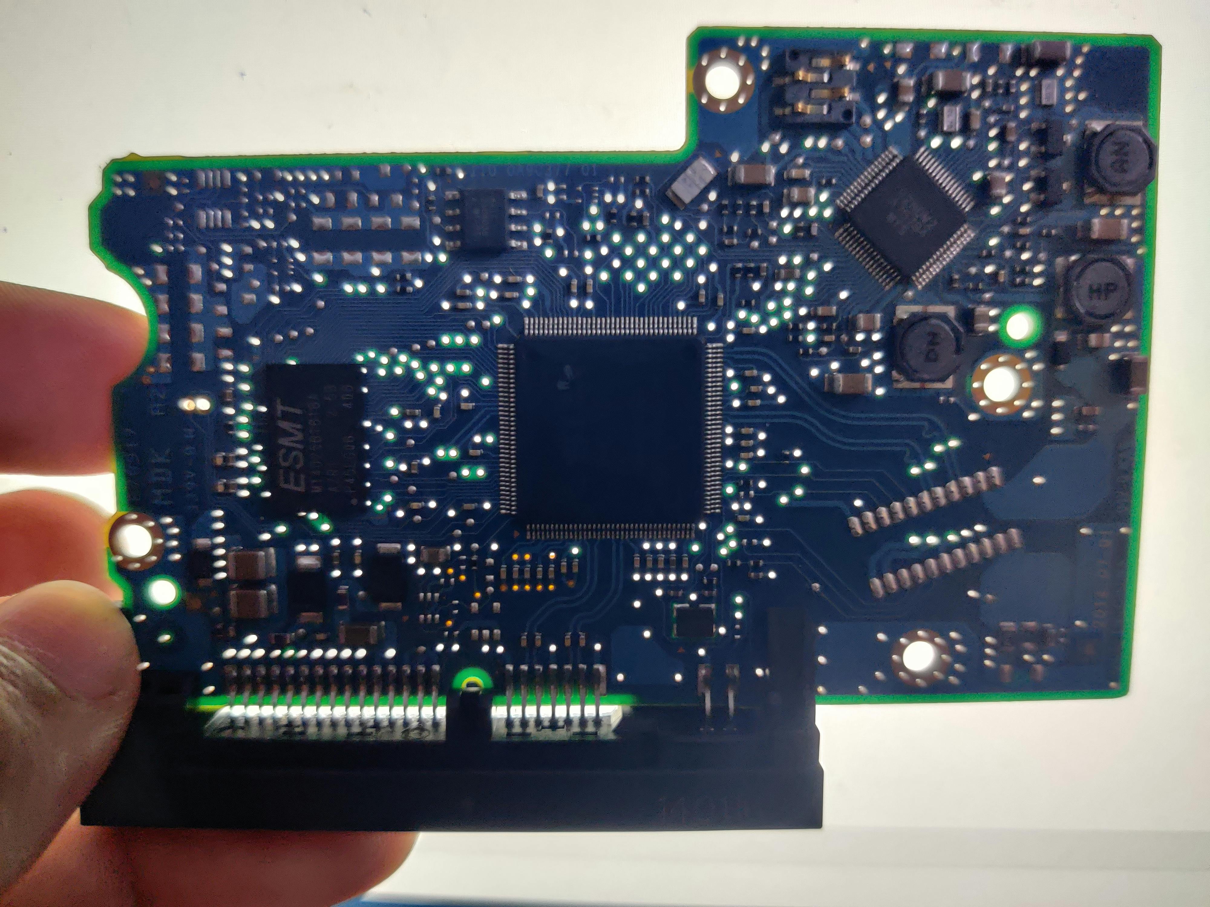 Now let’s have a little fun analysing the PCB, so the main chip is an LSI - 6045 which is custom microcontroller for this hard disk. This PCB is a multilayer PCB with many holes between the layers, which I assume would make the manufacturing much more expensive, but does allow it to be a lot smaller. It was interesting to see how the PCB was connected to the inside, by a small 22 pin contact, which meant it had to right in place, even a small alignment issue and it wouldn’t work. The PCB has a lot of capacitors and a few resistors and 3 inductors, have used the smallest possible package size, which make them impossible to see without a microscope. Other components on this board are ESMT W14D2581818A, which I assume is some sort of flash or cache or something. I don’t have any experience with data storage protocols or techniques or anything related to it, maybe in the future when I have more knowledge about it, I might be able to understand this PCB better, but till there is nothing more I can get from this.