MATLAB State flow Deployment on Arduino

Hi, this blog is a way to keep all my projects in one place, while documenting the process along with all the problems that I encounter.
Hello, it’s been a while since I have written a blog, that is because I have started working. Today I am going to use the knowledge I have learned from my working experiences to create a very useful blog. I am going to try and bridge the gap between industry and university. In university we learn how to write code and how to blink an LED. However, industrial projects are must more complex. There are a set of procedures followed in the industry to make sure big projects are organized. One of the procedures is the flow of software development.
Today I am going to be doing a simple project where a led is lit based on the status of a pushbutton, however I would do it in a way which it would be done at a company. First creating a MATLAB model and then generating code and porting it on the hardware.
SOFTWARE DEVELOPMENT
The development of such a big project follows a certain procedure. First the requirements of the system are decided, many months may be spent on deciding the requirements, but after the requirements are finalized, there will be no change or addition to these requirements. With these requirements the basic control and functionality is decided. Once these details are ironed out the hardware can be chosen, the component section is a long and important step. There are many parameters that must be taken in this stage, for example if the car is to be ASIL-D certified, then only components with such certification must be chosen. Similarly, if it is decided that there has to be 82 digital inputs and 14 analog inputs then a microcontroller with a minimum of these pins must be chosen. To choose the right component, first a list of all the available components that fit the requirements are noted, then a comparison is run on all the whole list, with parameters such as price and support taken into account. After these steps are completed the software and hardware design can begin. In the hardware design, the first step is the schematic design, followed by placement and routing. The PCB is then manufactured, assembled and tested. Based on the results, observations and revisions are made.
The software development runs in parallel to the hardware development and consists of many subsections. The software is mainly of three layers. First are the low-level drivers, this layer is specific to the board. In this layer, firmware will be developed to interface the different peripherals. The input to this layer is the physical voltages to the microcontroller and the output to his layer is certain functions and variables. These function APIs are documented and passed on to the middle layer. An example of this would be readpin API, which is a function which will read the physical values of GPIO input and store its value in a variable.
The topmost layer is the application layer, the engineer involved in the application layer will work on developing algorithms for the different functionality of the system and implementing this on code. Most of the time, this process is done on MATLAB state flow. This is called model-based development and the engineers working on this layer need not know how to program in C, they must be profound in algorithm development and model-based development. These engineers do not know anything about the hardware or parts of the microcontroller, they will just develop state charts to perform the functions according to the requirements. After the state charts are created, one can click on generate code in the embedded coder library of MATLAB and C code will be generated according to the parameters set, this code will be irrespective of hardware, there will be certain input variables which have to be set, once these variables are updated the main code will run, which mostly included if else statements. After the code runs it will update certain output variables according to the algorithm implemented.
The middle layer is also known as the linking layer, the job of this layer is to take the API and backend variables from the low-level drivers and integrate it with the top layer variables present in the application layer. This is a very difficult procedure which involves collaboration from the whole team. If the hardware is changed in the future and a different microcontroller is used, then the low layer must be redone as well as the linking layer, while the application layer can remain the same. The advantage of such a workflow is that it allows different teams to work in parallel in order to reduce the timeline, it also for more flexibility and changes in the future.
Let me explain this flow with a simple example where a push of a button will turn on an LED. When the button is pushed, there is a voltage change on the microcontroller, this is detected by the lower layer. The linking layer will call the readpin API on the specific pin which the hardware is connected to, it will also store the result of the API in the backend variable which corresponds to the button. The middle layer will then link this low layer variable with the application layer. After updating the application layer input variables, the application will run and the output variables of the application layer will be updated. The linking layer will then update the lower layer variable based on the value of the corresponding variable in the application layer. Finally, the set pin API will be called which will drive the physical pin HIGH or LOW depending on the value of the variable. This is the complete flow of the software development.
SCOPE
Now that we know what the flow of software development is we can get started with out project. First, we will create a simple state flow on MATLAB which will turn an LED on if the pushbutton is pressed and off, if it is not pressed.
Then we will use the embedded coder application in MATLAB to generate C code of the state flow. Finally, we will convert the code into an Arduino code and run it on hardware, additionally we can try the same on the STM32 F407 discovery board as well.
MATLAB MODEL
Let’s first start by creating our state flow. State flow in MATLAB is very simple, you don’t really need to learn it, most of it is very intuitive. It’s like creating an algorithm on paper.
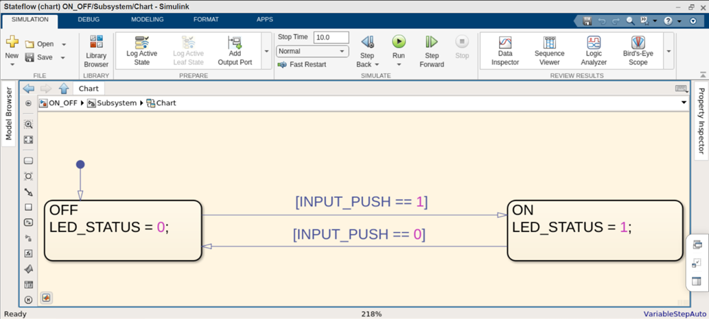
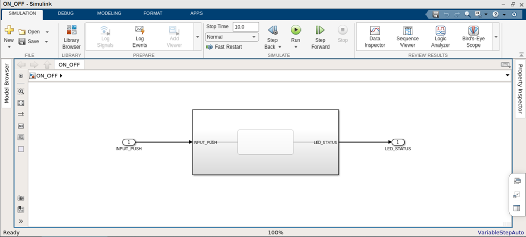
We have two states ON and OFF and we can switch between states with the INPUT_PUSH variable. Now that we have our algorithm, we can group this into a block and add an import and outport block.
CODE GENERATION
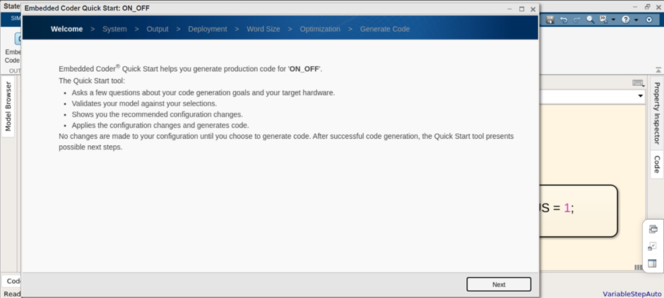
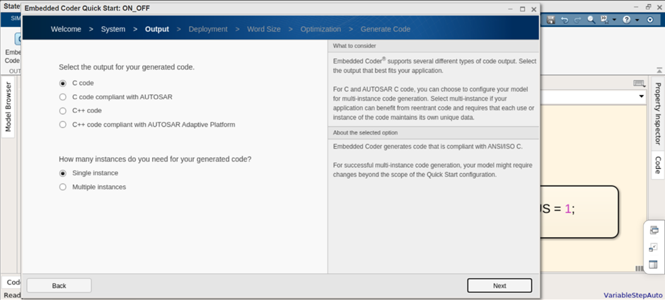
Now that we have completed the model, we can open the embedded coder and start to generate code. There are two ways to generate code. One with the STM libraries which will generate code for the algorithm as well as driver code. This method would require some more work. We can use the second method where only the algorithm code is generated and we will write the driver code by ourselves.
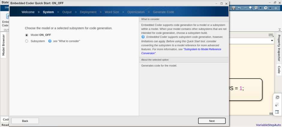
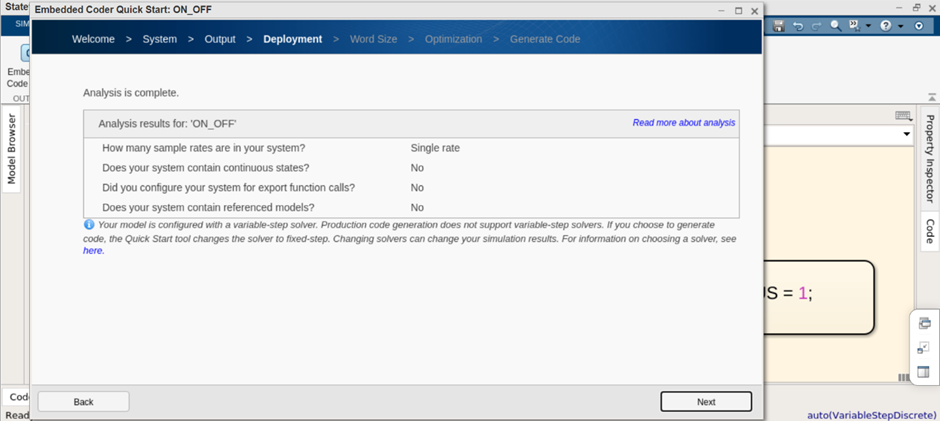
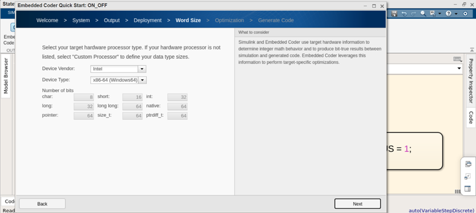
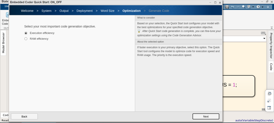
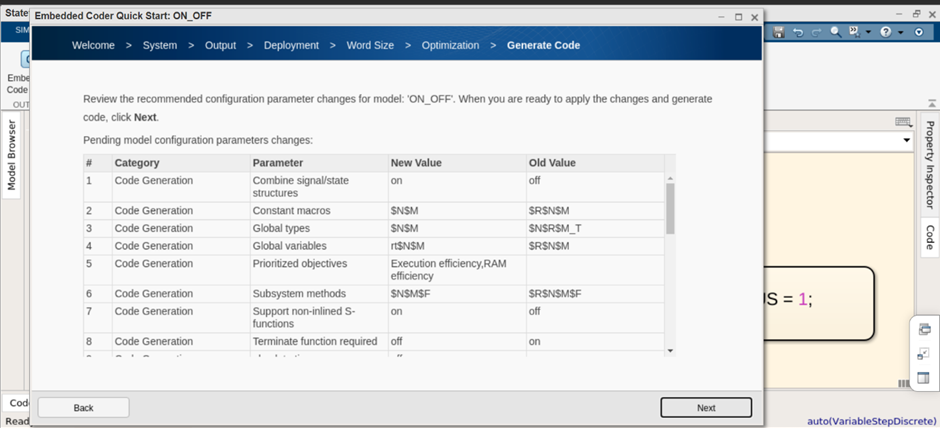
All we do is open the embedded coder and click on quick start assistance. Since ours is a simple project there is not much settings to do. I am going to leave all the settings as default. I will attach screenshots so that you can see.
DRIVER CODE
At the end we get 4 files. I’ll go through each one and explain what it contains.
ON_OFF.c
/*
 * File: ON_OFF.c
 *
 * Code generated for Simulink model 'ON_OFF'.
 *
 * Model version                  : 1.4
 * Simulink Coder version         : 9.7 (R2022a) 05-Jul-2022
 * C/C++ source code generated on : Sat Aug  6 08:52:49 2022
 *
 * Target selection: ert.tlc
 * Embedded hardware selection: Intel->x86-64 (Windows64)
 * Code generation objectives:
 *    1. Execution efficiency
 *    2. RAM efficiency
 * Validation result: Not run
 */

#include "ON_OFF.h"
#include "rtwtypes.h"

/* Named constants for Chart: '<S1>/Chart' */
#define IN_OFF                         ((uint8_T)1U)
#define IN_ON                          ((uint8_T)2U)

/* Block signals and states (default storage) */
DW rtDW;

/* External inputs (root inport signals with default storage) */
ExtU rtU;

/* External outputs (root outports fed by signals with default storage) */
ExtY rtY;

/* Real-time model */
static RT_MODEL rtM_;
RT_MODEL *const rtM = &rtM_;

/* Model step function */
void ON_OFF_step(void)
{
  /* Chart: '<S1>/Chart' incorporates:
   *  Inport: '<Root>/INPUT_PUSH'
   */
  if (rtDW.is_active_c3_ON_OFF == 0U) {
    rtDW.is_active_c3_ON_OFF = 1U;
    rtDW.is_c3_ON_OFF = IN_OFF;

    /* Outport: '<Root>/LED_STATUS' */
    rtY.LED_STATUS = 0.0;
  } else if (rtDW.is_c3_ON_OFF == IN_OFF) {
    if (rtU.INPUT_PUSH == 1.0) {
      rtDW.is_c3_ON_OFF = IN_ON;

      /* Outport: '<Root>/LED_STATUS' */
      rtY.LED_STATUS = 1.0;
    } else {
      /* Outport: '<Root>/LED_STATUS' */
      rtY.LED_STATUS = 0.0;
    }

    /* case IN_ON: */
  } else if (rtU.INPUT_PUSH == 0.0) {
    rtDW.is_c3_ON_OFF = IN_OFF;

    /* Outport: '<Root>/LED_STATUS' */
    rtY.LED_STATUS = 0.0;
  } else {
    /* Outport: '<Root>/LED_STATUS' */
    rtY.LED_STATUS = 1.0;
  }

  /* End of Chart: '<S1>/Chart' */
}

/* Model initialize function */
void ON_OFF_initialize(void)
{
  /* (no initialization code required) */
}

/*
 * File trailer for generated code.
 *
 * [EOF]
 */
This file contains the main functions of the algorithm. The ON_OFF_step function is a function with mainly if else conditions which basically describe the algorithm we created. As we don’t have any initiallizations the ON_OFF_initialize function is empty.
ON_OFF.h
/*
 * File: ON_OFF.h
 *
 * Code generated for Simulink model 'ON_OFF'.
 *
 * Model version                  : 1.4
 * Simulink Coder version         : 9.7 (R2022a) 05-Jul-2022
 * C/C++ source code generated on : Sat Aug  6 08:52:49 2022
 *
 * Target selection: ert.tlc
 * Embedded hardware selection: Intel->x86-64 (Windows64)
 * Code generation objectives:
 *    1. Execution efficiency
 *    2. RAM efficiency
 * Validation result: Not run
 */

#ifndef RTW_HEADER_ON_OFF_h_
#define RTW_HEADER_ON_OFF_h_
#ifndef ON_OFF_COMMON_INCLUDES_
#define ON_OFF_COMMON_INCLUDES_
#include "rtwtypes.h"
#include "rtw_continuous.h"
#include "rtw_solver.h"
#endif                                 /* ON_OFF_COMMON_INCLUDES_ */

/* Model Code Variants */

/* Macros for accessing real-time model data structure */
#ifndef rtmGetErrorStatus
#define rtmGetErrorStatus(rtm)         ((rtm)->errorStatus)
#endif

#ifndef rtmSetErrorStatus
#define rtmSetErrorStatus(rtm, val)    ((rtm)->errorStatus = (val))
#endif

/* Forward declaration for rtModel */
typedef struct tag_RTM RT_MODEL;

/* Block signals and states (default storage) for system '<Root>' */
typedef struct {
  uint8_T is_active_c3_ON_OFF;         /* '<S1>/Chart' */
  uint8_T is_c3_ON_OFF;                /* '<S1>/Chart' */
} DW;

/* External inputs (root inport signals with default storage) */
typedef struct {
  real_T INPUT_PUSH;                   /* '<Root>/INPUT_PUSH' */
} ExtU;

/* External outputs (root outports fed by signals with default storage) */
typedef struct {
  real_T LED_STATUS;                   /* '<Root>/LED_STATUS' */
} ExtY;

/* Real-time Model Data Structure */
struct tag_RTM {
  const char_T * volatile errorStatus;
};

/* Block signals and states (default storage) */
extern DW rtDW;

/* External inputs (root inport signals with default storage) */
extern ExtU rtU;

/* External outputs (root outports fed by signals with default storage) */
extern ExtY rtY;

/* Model entry point functions */
extern void ON_OFF_initialize(void);
extern void ON_OFF_step(void);

/* Real-time Model object */
extern RT_MODEL *const rtM;

/*-
 * The generated code includes comments that allow you to trace directly
 * back to the appropriate location in the model.  The basic format
 * is <system>/block_name, where system is the system number (uniquely
 * assigned by Simulink) and block_name is the name of the block.
 *
 * Use the MATLAB hilite_system command to trace the generated code back
 * to the model.  For example,
 *
 * hilite_system('<S3>')    - opens system 3
 * hilite_system('<S3>/Kp') - opens and selects block Kp which resides in S3
 *
 * Here is the system hierarchy for this model
 *
 * '<Root>' : 'ON_OFF'
 * '<S1>'   : 'ON_OFF/Subsystem'
 * '<S2>'   : 'ON_OFF/Subsystem/Chart'
 */
#endif                                 /* RTW_HEADER_ON_OFF_h_ */

/*
 * File trailer for generated code.
 *
 * [EOF]
 */
This file exits to support the ON_OFF.c file. This file contains all the enums, structures, deinfes, includes and function prototypes inorder to keep the .c file clean. There is no need to go through this file in detail. The .c files includes it anyway.
rtwtypes.h
/*
 * File: rtwtypes.h
 *
 * Code generated for Simulink model 'ON_OFF'.
 *
 * Model version                  : 1.4
 * Simulink Coder version         : 9.7 (R2022a) 05-Jul-2022
 * C/C++ source code generated on : Sat Aug  6 08:52:49 2022
 *
 * Target selection: ert.tlc
 * Embedded hardware selection: Intel->x86-64 (Windows64)
 * Code generation objectives:
 *    1. Execution efficiency
 *    2. RAM efficiency
 * Validation result: Not run
 */

#ifndef RTWTYPES_H
#define RTWTYPES_H

/* Logical type definitions */
#if (!defined(__cplusplus))
#ifndef false
#define false                          (0U)
#endif

#ifndef true
#define true                           (1U)
#endif
#endif

/*=======================================================================*
 * Target hardware information
 *   Device type: Intel->x86-64 (Windows64)
 *   Number of bits:     char:   8    short:   16    int:  32
 *                       long:  32    long long:  64
 *                       native word size:  64
 *   Byte ordering: LittleEndian
 *   Signed integer division rounds to: Zero
 *   Shift right on a signed integer as arithmetic shift: on
 *=======================================================================*/

/*=======================================================================*
 * Fixed width word size data types:                                     *
 *   int8_T, int16_T, int32_T     - signed 8, 16, or 32 bit integers     *
 *   uint8_T, uint16_T, uint32_T  - unsigned 8, 16, or 32 bit integers   *
 *   real32_T, real64_T           - 32 and 64 bit floating point numbers *
 *=======================================================================*/
typedef signed char int8_T;
typedef unsigned char uint8_T;
typedef short int16_T;
typedef unsigned short uint16_T;
typedef int int32_T;
typedef unsigned int uint32_T;
typedef long long int64_T;
typedef unsigned long long uint64_T;
typedef float real32_T;
typedef double real64_T;

/*===========================================================================*
 * Generic type definitions: boolean_T, char_T, byte_T, int_T, uint_T,       *
 *                           real_T, time_T, ulong_T, ulonglong_T.           *
 *===========================================================================*/
typedef double real_T;
typedef double time_T;
typedef unsigned char boolean_T;
typedef int int_T;
typedef unsigned int uint_T;
typedef unsigned long ulong_T;
typedef unsigned long long ulonglong_T;
typedef char char_T;
typedef unsigned char uchar_T;
typedef char_T byte_T;

/*=======================================================================*
 * Min and Max:                                                          *
 *   int8_T, int16_T, int32_T     - signed 8, 16, or 32 bit integers     *
 *   uint8_T, uint16_T, uint32_T  - unsigned 8, 16, or 32 bit integers   *
 *=======================================================================*/
#define MAX_int8_T                     ((int8_T)(127))
#define MIN_int8_T                     ((int8_T)(-128))
#define MAX_uint8_T                    ((uint8_T)(255U))
#define MAX_int16_T                    ((int16_T)(32767))
#define MIN_int16_T                    ((int16_T)(-32768))
#define MAX_uint16_T                   ((uint16_T)(65535U))
#define MAX_int32_T                    ((int32_T)(2147483647))
#define MIN_int32_T                    ((int32_T)(-2147483647-1))
#define MAX_uint32_T                   ((uint32_T)(0xFFFFFFFFU))
#define MAX_int64_T                    ((int64_T)(9223372036854775807LL))
#define MIN_int64_T                    ((int64_T)(-9223372036854775807LL-1LL))
#define MAX_uint64_T                   ((uint64_T)(0xFFFFFFFFFFFFFFFFULL))

/* Block D-Work pointer type */
typedef void * pointer_T;

#endif                                 /* RTWTYPES_H */

/*
 * File trailer for generated code.
 *
 * [EOF]
 */
This file can also be mostly ignored, it contains all the variable type definition and variable sizes, MATLAB uses its own variable types in the .c and .h files. It then defines its variables in terms of standard variables using this file. It is included in both the .c and .h files.
ert_main.c
/*
 * File: ert_main.c
 *
 * Code generated for Simulink model 'ON_OFF'.
 *
 * Model version                  : 1.4
 * Simulink Coder version         : 9.7 (R2022a) 05-Jul-2022
 * C/C++ source code generated on : Sat Aug  6 08:52:49 2022
*
 * Target selection: ert.tlc
 * Embedded hardware selection: Intel->x86-64 (Windows64)
 * Code generation objectives:
 *    1. Execution efficiency
 *    2. RAM efficiency
 * Validation result: Not run
 */

#include <stddef.h>
#include <stdio.h>            /* This example main program uses printf/fflush */
#include "ON_OFF.h"                    /* Model header file */

/*
 * Associating rt_OneStep with a real-time clock or interrupt service routine
 * is what makes the generated code "real-time".  The function rt_OneStep is
 * always associated with the base rate of the model.  Subrates are managed
 * by the base rate from inside the generated code.  Enabling/disabling
 * interrupts and floating point context switches are target specific.  This
 * example code indicates where these should take place relative to executing
 * the generated code step function.  Overrun behavior should be tailored to
 * your application needs.  This example simply sets an error status in the
 * real-time model and returns from rt_OneStep.
 */
void rt_OneStep(void);
void rt_OneStep(void)
{
  static boolean_T OverrunFlag = false;

  /* Disable interrupts here */

  /* Check for overrun */
  if (OverrunFlag) {
    rtmSetErrorStatus(rtM, "Overrun");
    return;
  }

  OverrunFlag = true;

  /* Save FPU context here (if necessary) */
  /* Re-enable timer or interrupt here */
  /* Set model inputs here */

  /* Step the model */
  ON_OFF_step();

  /* Get model outputs here */

  /* Indicate task complete */
  OverrunFlag = false;

  /* Disable interrupts here */
  /* Restore FPU context here (if necessary) */
  /* Enable interrupts here */
}

/*
 * The example main function illustrates what is required by your
 * application code to initialize, execute, and terminate the generated code.
 * Attaching rt_OneStep to a real-time clock is target specific. This example
 * illustrates how you do this relative to initializing the model.
 */
int_T main(int_T argc, const char *argv[])
{
  /* Unused arguments */
  (void)(argc);
  (void)(argv);

  /* Initialize model */
  ON_OFF_initialize();

  /* Attach rt_OneStep to a timer or interrupt service routine with
   * period 0.2 seconds (base rate of the model) here.
   * The call syntax for rt_OneStep is
   *
   *  rt_OneStep();
   */
  printf("Warning: The simulation will run forever. "
         "Generated ERT main won't simulate model step behavior. "
         "To change this behavior select the 'MAT-file logging' option.\n");
  fflush((NULL));
  while (rtmGetErrorStatus(rtM) == (NULL)) {
    /*  Perform application tasks here */
  }

  return 0;
}

/*
 * File trailer for generated code.
 *
 * [EOF]
 */
This is the main .c file. But think of it more of an example or reference to create our own .ino file for Arduino. ALL we really have to do is to add our inputs before the rt_Onestep() function and the outputs after the function. Then we can call this function in our main loop. Refer bellow for my .ino file. I removed some of the comments to make the code easier to read.
#include <stddef.h>
#include "ON_OFF.c"
#define pusbutton 3
#define led 2


void setup()
{
    Serial.begin(9600);
    pinMode(pusbutton,INPUT);
    pinMode(led,OUTPUT);
}

void loop()
{
  rt_OneStep();
  delay(100);
}


void rt_OneStep(void)
{
  static boolean_T OverrunFlag = false;

  /* Check for overrun */
  if (OverrunFlag) {
    rtmSetErrorStatus(rtM, "Overrun");
    return;
  }

  OverrunFlag = true;

  /* Set model inputs here */
  rtU.INPUT_PUSH = digitalRead(pusbutton);

  /* Step the model */
  ON_OFF_step();

  /* Get model outputs here */
  digitalWrite(led,rtY.LED_STATUS);

  /* Indicate task complete */
  OverrunFlag = false;
}
I assigened the push button to pin 3 and the led to pin 2. I called the digital read and digital write function near the main step function.
DEBUGGING
I was getting the error that rtM was defined twice so I went to the ON_OFF.h file and commented the following line.
/* Real-time Model object */
//extern RT_MODEL *const rtM;
After doing so the code compiled successfully. No other debugging was required.
Hardware
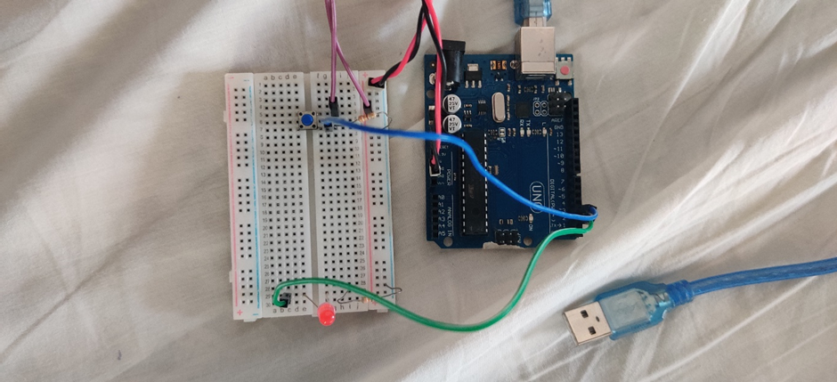
I then made the hardware connection with the led and push button, making sure to add resistors.
CONCLUSION
Find the demonstration at : https://youtu.be/-XqxTJhC-iE
In this project I was able to explain the programming flow with a simple example. Now we can try exploring more complex projects as well.


