Hi, this blog is a way to keep all my projects in one place, while documenting the process along with all the problems that I encounter.
In a previous project I had implement a basic IR remote using an Arduino and an IR LED. The project was successful and the prototype worked quite well. However, I did not feel like I learnt enough during the project, this is because I used the IR remote library which took care of most of it. I want to implement this project on an STM32 F4 discovery board. In order to implement it on an ARM based board, I should first be able to implement by remote on an Arduino without the use of libraries, which is exactly what I will be doing in this project. By the end of this project, I should be able to get the same output as the previous project however without using any libraries. You can read about my previous project here.
Protocol
The first thing I would need to learn is what kind of protocol my remote is using, I have actually already found this out in the previous project, my remotes are using a NEC protocol, which is fairly common. In order to implement this protocol, I would need to learn about the quirks of this protocol. Different IR remotes use different protocols as demonstrated in this rather interesting Wikipedia article. In order to make a remote I first need to understand the signal sent by the remote. This can be done by hooking up an oscilloscope to the TSOP1738. However, with me being at home, and not having a DSO I cannot do this. Luckily, I have found a video online where they actually do this. In this video he does go on to explain the protocol as well, you can watch the YouTube video here.
NEC
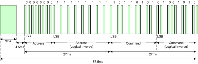
The output signal actually consists of two signals, the carrier signal and the data signal. The carrier signal is encoded into the data signal to help carry the data, but it does not as such have any useful information. The carrier signal is just a square wave signal set at a fixed frequency. An important thing to note is that the signal is normally high and when the signal starts it goes low. There is first a long “low” signal sent. In this the block the carrier frequency is set. Each signal after that is around 550us. This is the time period for which the “1” or “0” lasts for, I will refer to this as the time_period. There is actually a small difference here. This is in the NEC protocol. For a “0” to be send the protocol actually send a “01” and for a “1” to be sent the protocol send a “0111”. You can find more information about the NEC protocol here. According to the NEC protocol specifications the signal we send must have the following parts
1) A start pulse burst (9ms long)
2) A space (4.5ms long)
3)An address for receiving data (8 bits)
4)Logical inverse of the address (8 bits)
5) A command (8 bits)
6)Logical inverse of command (8 bits)
7) A ending pulse burst (526.5us)
Code
Now that we know what we have to send let us start writing a code to send such a signal. I came up with a code with the help of this reference from EEVblog
#define IRLed 3 //pin connected to the IR LED
unsigned long input_code=0b00100000110111111101000000101111; //this is the code for the input button of the remote
unsigned long power_code=0b00100000110111110001000011101111; //this is the code for the power button of the remote

void setup() {
  pinMode(IRLed, OUTPUT); //initializing the IR led as an output
}

void loop() {
  data_signal(power_code);
  delay(5000);
  for (int i=0;i<6;i++){
    data_signal(input_code);
    delay(3000);
  }
  delay(10000);
}

void carrier_signal(unsigned int t_micro){ //function to turn on and of the LED correspoding to the carrier frequency
  for (int i=0; i<(t_micro / 26); i++){ //26 because 1/38==26, 38 is the carrier frequency
    digitalWrite(IRLed, HIGH);
    delayMicroseconds(9); //should be 13 but the function takes 3micro seconds to excicute which has to be compensated
    digitalWrite(IRLed, LOW);
    delayMicroseconds(9); //should be 13 but the function takes 3micro seconds to excicute which has to be compensated
  }
}

void data_signal(unsigned long code){
  carrier_signal(9000); //starting burst of 9ms
  delayMicroseconds(4500); //wait time of 4.5ms

  int time_period=562; //time for each one and each zero
  for (int j=0;j<32;j++){ //for each of the 32 bits in the signal code
    carrier_signal(time_period);  //first bit is always low
      if (code & 0x80000000){      //mask to get msb, if bit is 1
        delayMicroseconds(3*time_period); //for high signal we need to send high signal 3 times
      }
      else{                // if bit is 0
        delayMicroseconds(time_period); //for low signal we need to send the signal only once
      }
   code<<=1;      //to bit shift to the next byte
  }
  carrier_signal(time_period); //seding stop bit
}
Now I will go through the code line by line and explain it.
Initializations
#define IRLed 3 //pin connected to the IR LED
unsigned long input_code=0b00100000110111111101000000101111; //this is the code for the input button of the remote
unsigned long power_code=0b00100000110111110001000011101111; //this is the code for the power button of the remote

void setup() {
  pinMode(IRLed, OUTPUT); //initializing the IR led as an output
}
The first line depends on which digital pin we use to connect the IR LED, I have used digital pin 3, you can use any other digital pin also. Then next two lines are the codes which I got from the previous experiment. I took the codes for the input button on the remote and the power button on the remote. I converted the hexadecimal numbers to binary so that it would be easier to understand. It is a 32-bit number, the first 8-bits is the address and the second 8-bits is the inverse of the address. The next 8-bits is the command followed by 8-bits of its inverse. Make sure to use the long integer otherwise there would be size issue. In the setup I set the pin 3 as output.
Main Loop
void loop() {
  data_signal(power_code);
  delay(5000);
  for (int i=0;i<6;i++){
    data_signal(input_code);
    delay(3000);
  }
  delay(10000);
}
In the main loop I press the power button once, wait for 5 seconds. Then click the input button 5 times with a 3 second delay in between after which I wait 10 seconds before repeating it again. This is just a demo to make sure everything is working, later I can change this or add and push button.
Carrier Wave
void carrier_signal(unsigned int t_micro){ //function to turn on and of the LED correspoding to the carrier frequency
  for (int i=0; i<(t_micro / 26); i++){ //26 because 1/38==26, 38 is the carrier frequency
    digitalWrite(IRLed, HIGH);
    delayMicroseconds(9); //should be 13 but the function takes 3micro seconds to excicute which has to be compensated
    digitalWrite(IRLed, LOW);
    delayMicroseconds(9); //should be 13 but the function takes 3micro seconds to excicute which has to be compensated
  }
}
This function implements the carrier signal, which is just a fixed frequency square wave. It takes one parameter, which is the time in micro seconds that it should run for. For the NEC protocol the carrier frequency is 38KHz so that would result in a 26-microsecond time period. So, we have to divide the time of the wave by 26 to create that many waves. We then just turn the pin high and then wait a while and then turn it low and wait. Both these waiting periods should add up to 26 micro seconds. However, the digital Write function take a substantial amount of time to execute, so we need to compensate for this time, hence instead of a 13 microsecond second delay we make it a 9-microsecond delay.
Data Signal
void data_signal(unsigned long code){
  carrier_signal(9000); //starting burst of 9ms
  delayMicroseconds(4500); //wait time of 4.5ms

  int time_period=562; //time for each one and each zero
  for (int j=0;j<32;j++){ //for each of the 32 bits in the signal code
    carrier_signal(time_period);  //first bit is always low
      if (code & 0x80000000){      //mask to get msb, if bit is 1
        delayMicroseconds(3*time_period); //for high signal we need to send high signal 3 times
      }
      else{                // if bit is 0
        delayMicroseconds(time_period); //for low signal we need to send the signal only once
      }
   code<<=1;      //to bit shift to the next byte
  }
  carrier_signal(time_period); //seding stop bit
}
In this function we implement the command that we need to send. It takes one parameter which is the command code (the 32-bit binary code we defined for each button). By looking at the NEC protocol we can see that there are few things we need to do before we send a signal. The first thing is a 9ms low signal (pulse burst) where we send the carrier frequency. This 9ms is also 16 times the pulse length of a logical data bit. To send this burst we carrier signal function and give the parameter as 9000. This is followed by a 4.5ms delay, we implement this with the delay Microsecond function. We then define a time_period as 562 which I had explained before. The next part of the code is to go through each bit of the 32-bit code and if it is a “0” we need to send a “01” and if it is a “1” we need to send a “0111”. To iterate through each bit, I have used a mask here. The concepts of masking the Most significant bit and bit shifting are quite new to me however it is a common method. I had tried a simpler and more intuitive method of dividing by the base (normally 10) and taking the remainder. However, I could not get that code to work but I have shown it bellow so as to get an idea of what it happening here.
unsigned int code_copy=0b0010011;
  int q=0;
  while(code_copy>0b0){
    q=code_copy%2;
    Serial.println(q);
    code_copy=code_copy/2;}
Results
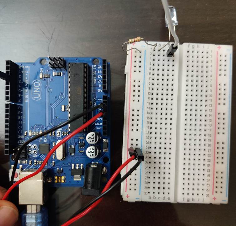
I was able to implement a simple IR remote and turn on the tv and change the input. This project is not successful as I got the same results as the previous project. Now what I plan on doing next is to use a STM32 board and implement this project along with adding more functionality there.
Reference
Codes for my remote:
Input button: 20DFD02F=00100000110111111101000000101111
Power button: 20DF10EF=00100000110111110001000011101111


