H Bridge
L293D Motor Driver Module

Hi, this blog is a way to keep all my projects in one place, while documenting the process along with all the problems that I encounter.
In a previous blog I mentioned that I had not done much work with motors. To change that, in this blog I would be working with motors and motor drivers. D.C motors are very common and inexpensive, but controlling these motors are not as straight forward, so in this project we are going to be working with a motor driver board.
D.C Motors
D.C. motors are very common, you can find them in toys and alarm clocks and almost every cheap electronics gadget you have. The reason for this is because D.C Motors are very inexpensive. Electro mechanical energy conversion is done easily through a motor. If you need to convert electrical energy into some mechanical movement the best and sometimes only way is a motor. Out of all the motors such as A.C motors, Induction Motors, etc. D.C motors are the cheapest and easiest to use. This is why they are very common. The exact working of the motor is beyond the scope of this blog but has to do with magnetism. You can watch this video if you are curious to learn about the working of a D.C motor.
In the end of the day all you need to know is that to make the motor turn clockwise you need to provide a positive voltage to one input and ground to the other input. To change the direction of rotation all you need to do is to change the polarity. This can be demonstrated this with a generic 12V D.C motor found in an old toy, you can find something similar here The motor would run at 5V but the rated voltage is 12V, so to get the best performance you can just connect one side of the motor to +12V and the other to ground. If you want to change the direction of rotation you can just interchange the terminals.
Now interchanging wires to change the direction is not a very feasible thing in a real time project. We need a better way of controlling the motor. One way we can do that is with a motor driver.
Motor driver
Motors drivers are actually very simple things. They are just an IC which will control the motor for us. We just have to tell the driver IC what we want and the IC will do it for us. Another thing motor driver IC do is help with voltage and current. Different motors have different rated voltages and most hobbyist motors tend to run on 12V. Since most microcontrollers run at 5V so we cannot just connect the motor terminals to two GPIO pins of the microcontroller and turn one high and one low, however this might be easy to do in certain applications.
Motors also tend to have a high peek current; this is because the motor will take a lot of current to start up but once it gets up to speed it does not require much current to keep the speed up. Micro controllers may not be able to provide this high transient current and it might even damage the microcontroller, for this reason we use motor driver IC made for these applications.
H-Bridge
You might hear people refer to motor drivers as H-Bridge this is because the module has 4 switches (Normally mosfets) out of which two closes at a time in order to power the motor, this is similar to a 4-pin push button.
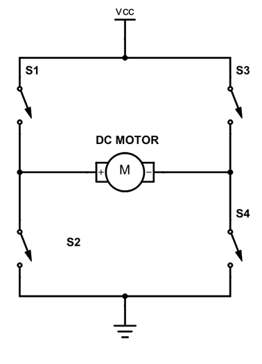
If S1 and S4 close and S3 and S4 are open then the motor would have VCC at its left terminal (+) and ground at the right terminal (-) which would turn the motor clockwise, if the switched S3 and S2 is closed and S1 and S4 is open then the motor runs in the anticlockwise direction.
L239D
There are many different H-Bridge modules available in the market. Today I’m going to be using a less common module based on the L239D IC. This is a two-motor module, meaning it can control two motors with one board.
Recently I have been wondering on how to wire up a car window interface. If I push one button then the window goes down and if I press another button then the window goes up, and if I press both buttons then nothing happens. Obviously, it is very simple to do with an Arduino but I was wondering how to do it without a microcontroller. I first though of using a relay, but then I realized that if I pressed both the buttons then there would be a big problem. That is where I go the idea of using a motor driver. I would just be using the L239D and two switches, no microcontroller or anything.
The L239D has 3 screw terminals: 12V, GND, 5V and 4 outputs. I will connect the 12V and 5V from two power supplies and connect the grounds together. I will then connect these grounds to the ground terminal. Ill connect output 1 to one probe of my multi meter and output 2 to the other multi meter probe.
There are 6 logic pins theses are: EN1, EN2, IN1, IN2, IN3 and IN4. EN1, IN1 and IN2 are for the motor one (out 1 and out 2) and the EN2, IN3 and IN4 are for the motor two (out 3 and out 4). EN1 stands for enable and must be connected to logic one if we want the circuit the function. IN1 and IN2 control the direction of the motor, if I connect one to ground and the other to positive 5V then the motor will spin in one direction and if I connect IN1 to 5V and IN2 to ground then the motor will spin in the other direction. The good part about this is that if I connect both to ground or both to 5V nothing happens, which is what I want.
Ill connect both EN1 and EN2 to 5V as these are the enable pins which needs to be connected to 5V for the output to be enabled. Ill connect IN1 and IN2 to the common terminal of two switches with one end connected to 5V and the other connected to GND.
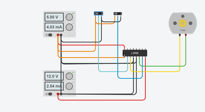
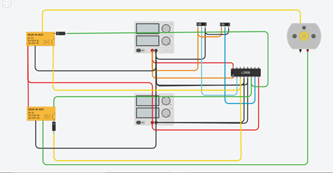
I made a simple simulation on tinkerCad. As you can see if both the switches are in the same position then there is no motion, however if only the second switch is the on position the motor moves clockwise and if only the first switch is in the on position the motor moves anticlockwise. Check out the simulation here
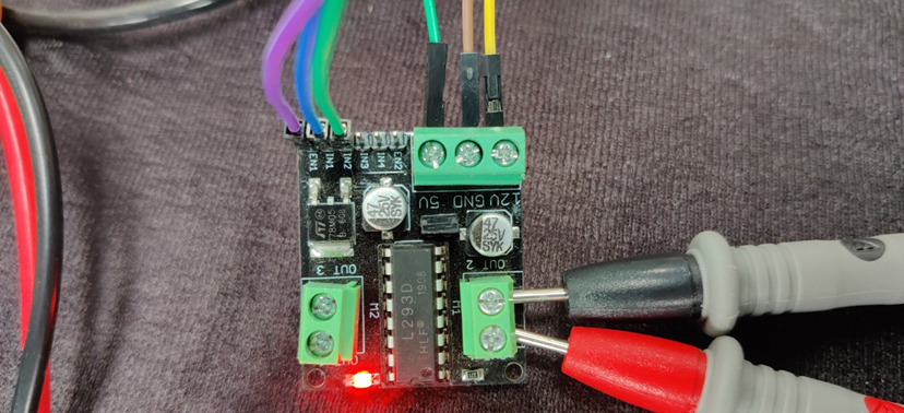
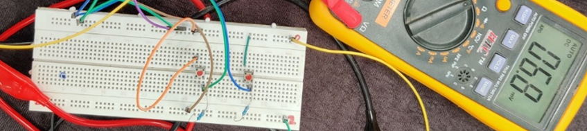
I also made the same circuit in hardware using a push button with a pull up resistor. I did not have a motor to test my circuit out so I am using a multi meter.
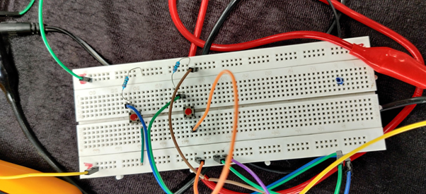
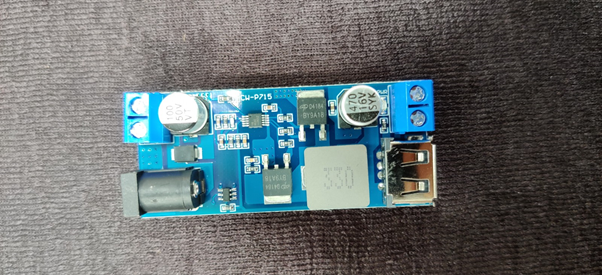
Providing two different voltage supplies is not easy, hence I’ll be using a 12V to 5V voltage converter board. You can find a similar one here this board will take a 12V input and produce a 5V output. I will use this to power the board and to control the switches.
Also my application requires more power than this module can provide hence I’ll be connection both outputs of the module in parallel.
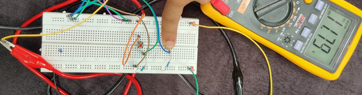
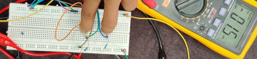
As you can see pressing one button gives me 12V and pressing the other button gives me -12V.
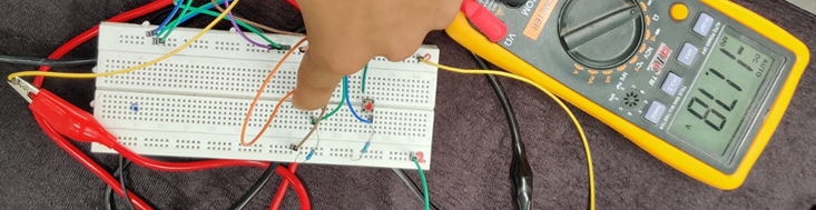
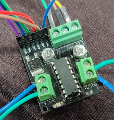
Further you can see that pressing both buttons or neither buttons do not give me any appreciable voltage and hence the motor is safe.
I made the follow design for a motor that would take huge amounts of current with the help of two relays and a diode.
You can check out the simulations here


