CRC Calculation Unit on STM 32 F4

Hi, this blog is a way to keep all my projects in one place, while documenting the process along with all the problems that I encounter.
Today we are going to implement CRC error detection on the STM 32 F407 microcontroller using the inbuild CRC module.
CRC
CRC stands for Cyclic redundancy check and it is an important tool in error detection. In a previous project I had implemented a parity checker with a xor gate a d flip flop (you can read it here). A parity checker is very good in detecting single bit flips as it only counts the number of ones. CRC is a much more complex and robust error detecting algorithm which can detect a range of errors. CRC is baes on the principle of dividing a number by a polynomial. If you divide 0b00110011 by a polynomial say 0b011 you get a remainder which is very different from what you would get if you used another number. To put it simply, CRC works on division with a polynomial.
If you want to understand the theory behind if you can check out this great video by ben eater .
STM32
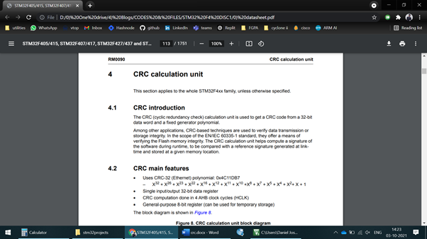
The STM32 has an inbuild CRC module which computes the CRC in hardware. According to the data sheet the CRC Calculation unit has a fixed polynomial and a single input/output data register.
Algorithm
All we have to do is to configure the crc unit, which involves enabling the clock from the RCC register and reset the CRC control register. We can then write the input value of which we want to compute the CRC to the data register and then wait for a few clock cycles for the CRC to be computed, we can then read the computed CRC and store it to a variable.
Code
#include "stm32f407xx.h"                                    //include heder file for the board

// Funciton Prototypes
void configurecrc(void);
void msDelay(uint32_t msTime);

uint32_t crc = 0X01010101;                            // Data to send
volatile uint32_t crcval;                                // variable to store the result

int main(){
    configurecrc();                                                // Configure CRC registers
    CRC->DR = crc;                                                // Give input to the crc value
    msDelay(500);
    crcval = CRC->DR;                                            // Read the CRC result
}

void configurecrc(void){
    RCC->AHB1ENR = (0X1UL<<12);                        // Enable CRC clock
    CRC->CR = (0X1UL<<0);                                    // Reset the CRC unit
}

void msDelay(uint32_t msTime)
{
    for (uint32_t i=0;i<msTime*4;i++)
    {
        __NOP();
    }
}
Output
I can run this code in debug mode and add the crcval variable to the watch window.
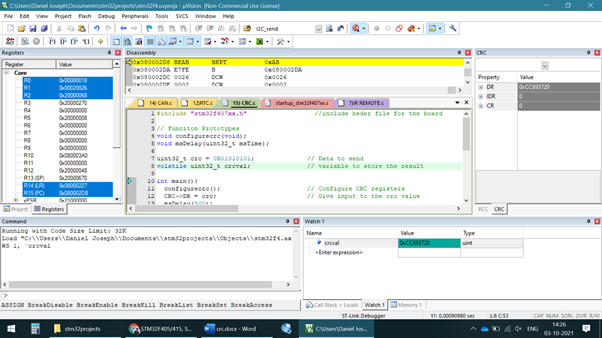
When the CRC unit is reset the data register gets the value 0xFFFFFFFF. After we write the values to the register, we can see the output almost immediately. We can check if this is correct on an online CRC calculator.
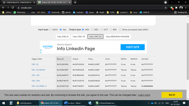
The algorithm implemented on the STM 32 is the CRC-32/MPEG-2 which is used in ethernet applications. As you can see the result is supposed to be 0xCC693720 which matches the result we obtained on the board.
Outcome
As the computation is implemented in hardware there is not much we have to do, and hence the very short code. This is not that great to understand CRC computation and how it works. Another disadvantage of this is that we can not change the CRC polynomial. This is a big problem as I wanted to implement a simple CRC-8 algorithm. On the flip side the computation is very fast as it is done in hardware. Nevertheless, to understand CRC better I will be implementing it in software in upcoming project. CRC computation is required for my FPGA IR project which I am doing as well as in the CAN protocol which I am working on.


