7 - Segment Display
Interfacing 7 Segment and DP switch with Altera Cyclone II EP2C5

Hi, this blog is a way to keep all my projects in one place, while documenting the process along with all the problems that I encounter.
Hey, so this is just a continuation of our previous project. We are today going to add a 7-segment display to the DIP switch project. This will hopefully be the fastest blog I have written to date.
I got my seven segment display from Tomson electronics Just make sure to note if you get the common anode or common cathode. I got a red common anode 7 segment display with a decimal point. I am not going to great detail explaining the 7 segment display but like always there is a perfect Ben Eater video for this, which you can watch here
Hardware
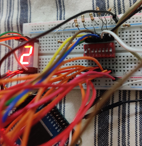
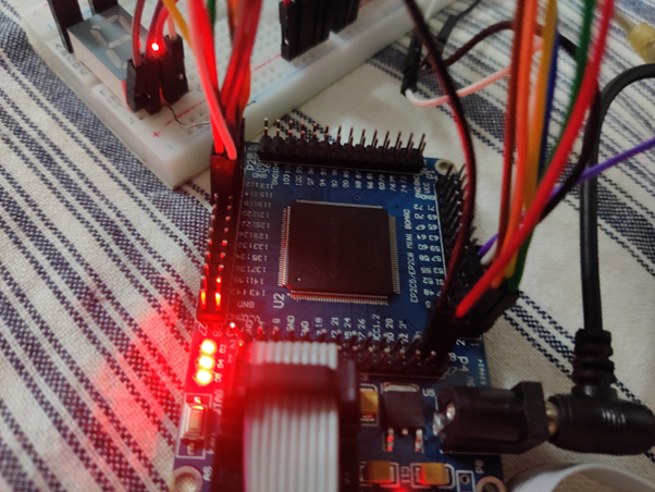
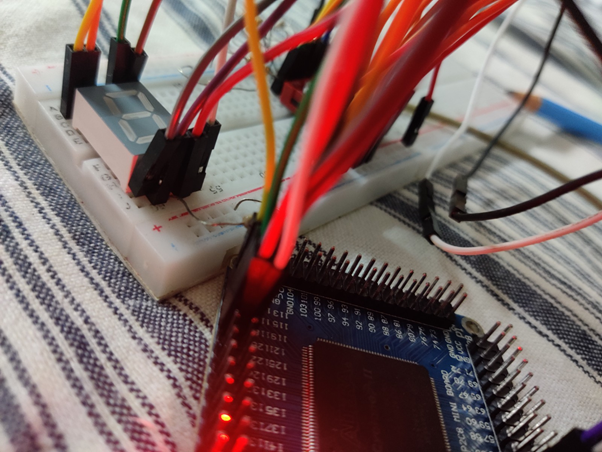
So, to get to connecting it, I put it on my breadboard and connected pin 3 to VCC through a pull up resistor. I used 330 ohms for this. You can also use pin 8 and both pin 3 and 8 are internally connected. The next thing to do is to connect the other pins to the FPGA, I used pins 112, 113, 114, 115, 118 and 119. I connected it with male to female jumper wires. The next step was to connect the DIP switch, I used the same thing from the previous blog, which you can read here The only difference is that I used all 8 switched this time, last time I only used 7.
![image.png] (https://cdn.hashnode.com/res/hashnode/image/upload/v1630343818147/rHk68s9v-.png)
Code
The code is similar to the previous project as well the only difference is each case statement, we have to change what comes in between the begin and end statements. This might not actually be that simple. I made a few notes to solve this.
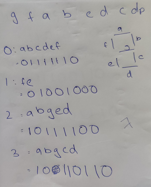
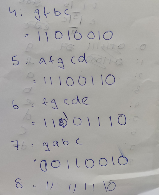
There were few decisions I had to take while making this, one I decided that I will only display numbers till 8, I won’t go into 2-digit numbers. I also decided that the switched would be directly corresponding to the number displayed and not some sort of encoder or decoder. Finally, I decided that if more than one switch was on, I would display the decimal point. This is just a basic project to understand Verilog, If, you want you can make a much more elaborate project.
module project1(a,b,c,d,e,f,g,h,seg1,seg2,seg3,seg4,seg5,seg6,seg7,seg8);
input a;
input b;
input c;
input d;
input e;
input f;
input g;
input h;
output seg1;
output seg2;
output seg3;
output seg4;
output seg5;
output seg6;
output seg7;
output seg8;

reg seg1,seg2,seg3,seg4,seg5,seg6,seg7,seg8;
wire a,b,c,d,e,f,g,h;

supply0 x;//turns on
supply1 z;//turns off

always @(a,b,c,d,e,f,g,h)
case({h,g,f,e,d,c,b,a})
8'b00000000:
begin
seg1=z;
seg2=x;
seg3=x;
seg4=x;
seg5=x;
seg6=x;
seg7=x;
seg8=z;
end

8'b00000001:
begin
seg1=z;
seg2=x;
seg3=z;
seg4=z;
seg5=x;
seg6=z;
seg7=z;
seg8=z;
end

8'b00000010:
begin
seg1=x;
seg2=z;
seg3=x;
seg4=x;
seg5=x;
seg6=x;
seg7=z;
seg8=z;
end

8'b00000100:
begin
seg1=x;
seg2=z;
seg3=x;
seg4=x;
seg5=z;
seg6=x;
seg7=x;
seg8=z;
end

8'b00001000:
begin
seg1=x;
seg2=x;
seg3=z;
seg4=x;
seg5=z;
seg6=z;
seg7=x;
seg8=z;
end

8'b00010000:
begin
seg1=x;
seg2=x;
seg3=x;
seg4=z;
seg5=z;
seg6=x;
seg7=x;
seg8=z;
end

8'b00100000:
begin
seg1=x;
seg2=x;
seg3=x;
seg4=z;
seg5=x;
seg6=x;
seg7=x;
seg8=z;
end

8'b01000000:
begin
seg1=z;
seg2=z;
seg3=x;
seg4=x;
seg5=z;
seg6=z;
seg7=x;
seg8=z;
end

8'b10000000:
begin
seg1=x;
seg2=x;
seg3=x;
seg4=x;
seg5=x;
seg6=x;
seg7=x;
seg8=z;
end

default
begin
seg1=z;
seg2=z;
seg3=z;
seg4=z;
seg5=z;
seg6=z;
seg7=z;
seg8=x;
end

endcase
endmodule
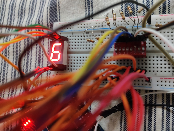
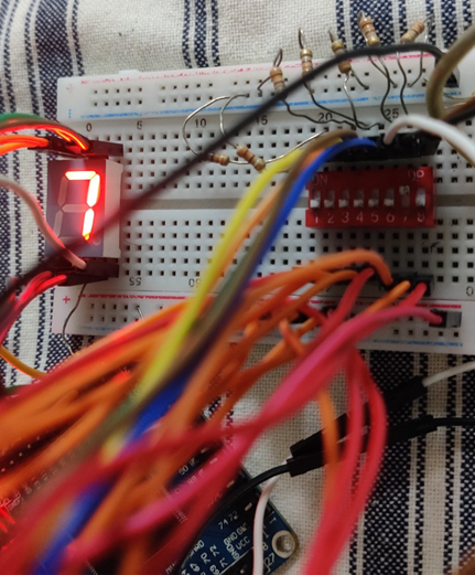
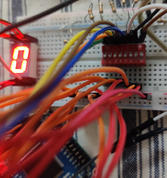
Output