Clock and 555 Timer
Hi, this blog is a way to keep all my projects in one place, while documenting the process along with all the problems that I encounter.
You hear a lot about clocks when dealing with digital electronics. I even talked about it in my project about I2C and parity checker. When you learn about flip flops and latches in digital electronics, the term “Clock” is used quite often. What is this clock, how to make one, why do we need it and how does it work? In this project I aim to understand those four questions practically.
What Is A Clock How to Make One
The first question: what is a clock? Put simply it is just a periodic signal. For a signal to be periodic it must have a changing value, but in electronics there is only two values, one and zero. Therefore, a clock is a periodic signal of one and zero. That is, a signal which changes from one to zero and back to one in a periodic manner. The period of the clock is determined by other factors but what is important is that this period is constant. If it is not clear as to what exactly it is yet, let us make a clock signal.
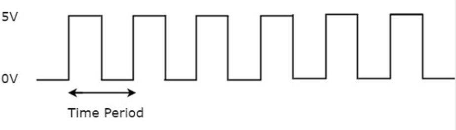
How to Make a Clock Signal
We actually did make a clock signal in our I2C project. We just need to turn a port high, wait for some time and then turn it low. In Arduino it is as simple as a digital Write, essentially the same as a blink LED program. The following code produces a clock signal on pin 1.
#define clock 1
void setup(){
pinMode(clock, INPUT);}
void loop(){
digitalWrite(clock, HIGH);
delay(100);
digitalWrite(clock, LOW);
delay(100);}
If I wanted to create a clock pulse on an 8051 microcontroller, I could write the following assembly code. There are many ways to do this, I am using timer 0 in mode 1 to create a 15ms clock on port P1.0
L:
SETB P1.0
ACALL DELAY
CLR P1.0
ACALL DELAY
SJMP L
DELAY:
MOV TMOD, #01H
MOV TH0, #0CAH
MOV TL0, #00H
SETB TR0
L1:
JNB TF0, L1
CLR TR0
CLE TF0
RET
END
Why Do We Need A Clock
Now having understood how to make a clock, we also got what a clock is. Let us understand why we need one. The best way to explain this is through the project about Data Transmission where I tried to communicate data between two Arduinos without a clock. The disadvantages of this project tell us why we need a clock. However, that project only talks about why we need a clock to transmit data. We need a clock for almost everything, for example, if you study a microcontroller, you would understand that a clock pulse if fundamental to its working. In essence, it is so that every process can be synchronized. If you think about it, a microprocessor is essentially just many different parts communicating with each other, the ALU and the Flash ROM and the RAM are all different components of the processor and they all must work together at the same speed to do different tasks.
Think of the clock as a metronome or beat, the different components (ALU, ROM, RAM, etc.) as the keys of the piano or the strings of a guitar and the fingers which strike the keys or form the chord as the data. Each time the metronome beats, a certain combination of keys is pressed or in the case of a guitar, the pick strikes the strings, with each string playing a different note. If there was no metronome or beat (i.e., the clock), each key will be played at a different time, causing chaos. Now that we understood what a single clock pulse is let us understand how a single instruction might use multiple clock pulses to accomplish the task. Here I am going to use the example of music sheet. For the sake of simplicity, we shall ignore all other notes other than quarter notes. Looking at only the first bar of the treble clef, the time signature is 4/4 and there are 4 notes in the bar, think of each note as a clock pulse and the whole bar as an instruction.
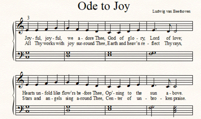
For example, the add instruction
ADD A,B
On the first clock cycle (the first note) the processor will go and find the op code for add function. On the second clock cycle (the second note) the value of A is found. The value in B is found on the third clock cycle (the third note) and finally the addition is computed by the ALU and the result is found on the fourth clock cycle (the third note). Therefore, we used 4 clock cycles to compute a single instruction, or 4 notes to play a single bar. This is just an example and it may vary with different processors and architectures. But, if we did not have a clock, we would be doing different thing at different times, or playing the notes at the wrong time and for the wrong duration. Therefore, a clock is required for synchronization and for different components to know when to execute the functions. Another example of a beating heart is given in this blog
How Does a Clock Work
Most microcontrollers use a crystal resonator/oscillator as their clock. The Arduino uno uses a 16MHz clock which is the silver color, shiny rectangular thing next to the D.C jack.
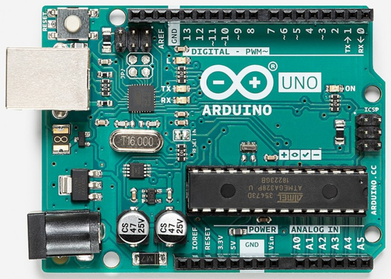
These type of crystal oscillators can be found everywhere and to understand how they work I suggest watching this video by Great Scott
555 Timer
Finally, after understanding these four questions it is time to do something practical. A 555 Timer IC is a reliable and cheap IC which can be found in timers, oscillators and pulse generation circuits. The internal working of the 555 timer is a bit complicated and many people have tried to explain it and have failed, however there is this really good video by Ben Eater which explains it perfectly. Now there are 3 modes to the 555 timer: The Astable, Monostable and Bistable modes.
Astable Mode
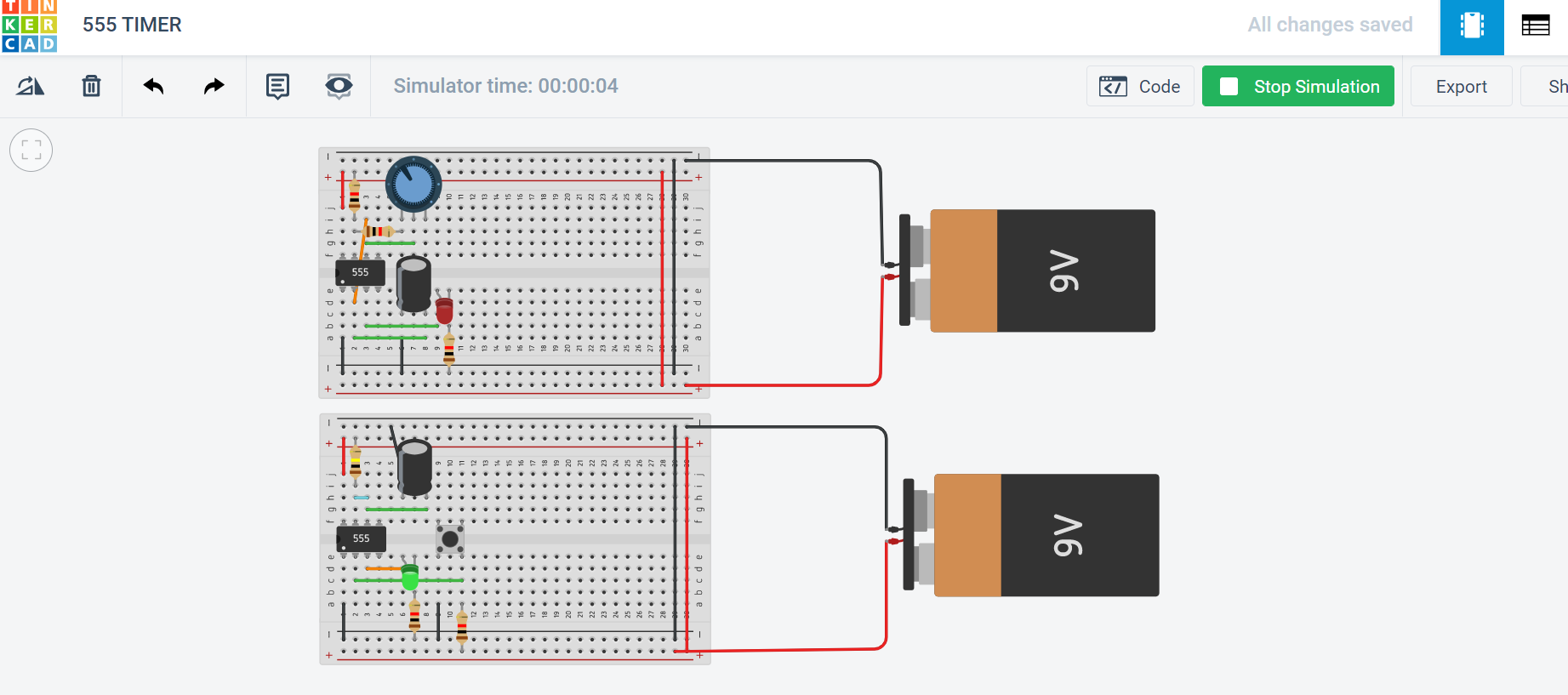
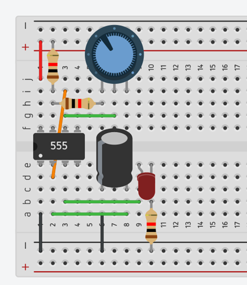
By using the 555 timer in the astable mode, we can create our own clock. This is what we could use when working with a microcontroller. The way it works is explained in this video. I used three 1k ohm resistors, a 1M ohm potentiometer and a 1uF capacitor.
Monostable Mode
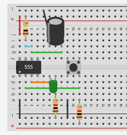
This is actually the reason I did this project. A 555 timer in Monostable mode can be used to debounce a switch. Yes, you can use an Arduino to debounce a switch but here I’m going to use this inexpensive 555 timer IC. Essentially, in the Monostable mode, the circuit will stay on for a certain about of time till it turns off. This is the principle of a debouncing circuit, each button press should be distinct and each press should be counted only once. An in dept explanation can be found here. For this circuit I used two 1kohm resistors with a 100kohm resistor and a 1uF capacitors to create a 0.1 second time period.
Bistable Mode
This is the third mode of the 555 timer. There isn’t really an interesting practical project with this mode, but if you want to understand how it works then click Here.
The name of the mode actually tells us what it does really. Astable means that it is not stable in either ON or OFF mode, therefore it oscillates between the ON and OFF. Monostable means it is stable in one mode, here that is the OFF mode, so even if you turn it ON it stays in that state for a while the IC waits for the capacitor to discharge and then goes back to it stable OFF state. Bistable means that is stable in both ON or OFF mode, so if you turn it, ON it will stay ON, or if you turn it OFF, it will stay OFF.
In this project I have understood, clocks and osculators as well as the 555 timer IC and its three modes.


