I2C and Parity Check

Hi, this blog is a way to keep all my projects in one place, while documenting the process along with all the problems that I encounter.
This project is a continuation of the previous project where I was transmitting data between two Arduinos. In the previous project we came across the issue of synchronization. We need the receiving Arduino to be ready to receive data, and the transmitting Arduino to tell the receiving station when it is transmitting and when it is not, it also needs both to run at the same speed. We solve this issue with the help of a clock, which is really just a pulse which is send before every character. So, this is another wire which is connected between them, therefore this is a two-wire communication methord. Think of it as talking, before sound comes out of our mouth, we see the mouth move, so when we see the mouth move, we understand that the person is saying something and we need to listen. If the person says something without opening their mouth, we aren’t ready for it, or if their mouth moves but no voice comes out, we feel odd. In a way the clock is ours eyes that see the movement of the mouth and the data line is our ears which listen to the sound. I guess that’s not the best example but there is nothing else I could come up with.
A clock pulse is just a symmetric square wave and its just turning on and off a port, it is widely used in electronics and computers to synchronize everything. So now let’s try the previous communication project except with a clock wire for synchronization.
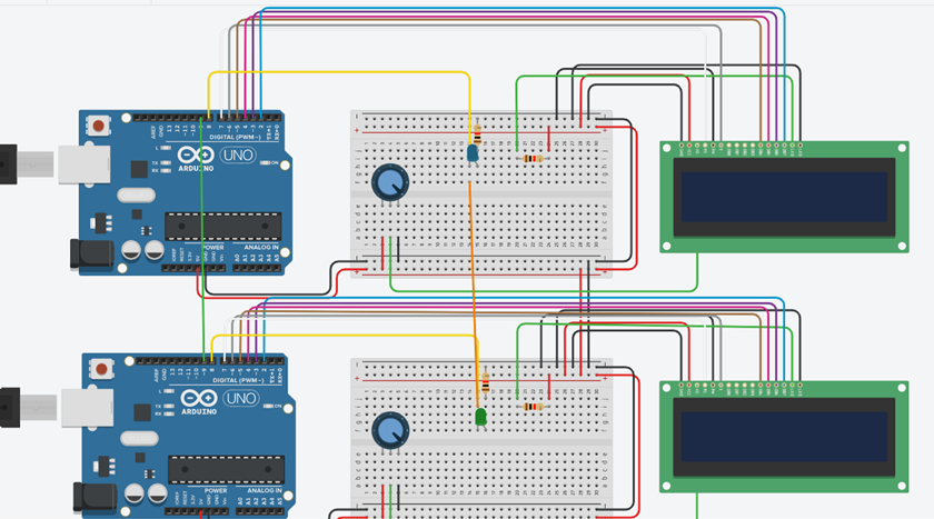
Hardware
I’m going to use the digital pin 9 to send the clock across. Its just a simple wire between both the pin 9’s. Other than that there is no change in the hardware
Code
First let’s think about the transmission side, all we need to do this send a high pulse every time we are transmitting a character. We can go as fast as the Arduino can go really, let’s say 50ms.
//transmission
#include <LiquidCrystal.h>
#define tx 8
#define clock 9
LiquidCrystal lcd(7,6,5,4,3,2);
char message[14]="10001001";
void setup()
{
  pinMode(tx, OUTPUT);
  pinMode(clock, OUTPUT);
  lcd.begin(16,2);
}

void loop()
{

  for (int i=0;i<strlen(message);i++){
  digitalWrite(clock,HIGH);
  delay(50);
  digitalWrite(clock,LOW);
   if (message[i]=='1'){
      digitalWrite(tx,1);
      lcd.print('1'); }
    else if (message[i]=='0'){
      digitalWrite(tx,0);
      lcd.print('0');    }

    delay(50);
  }}
So, for the receiver I shall use interrupts, because they are amazing. An interrupt is basically a sort of shout, every time the interrupt pin is high the Arduino gets a shout and it has to do a specific task, after which it goes back to what it was doing. I haven’t implemented interrupts in Arduino before but it should be pretty easy. To learn more about Arduino interrupts I’m going to do a bit of research on it and by research, I mean I’ll go watch one YouTube video on it. First thing is actually interrupts can only be used on port 3 and 2, so I’m going to move around the wires but nothing changed fundamentally, just a shift in wires and that will be reflected in the code.
//receiving
#include <LiquidCrystal.h>
#define rx 8
#define clock 2
LiquidCrystal lcd(7,6,5,4,3,1);
volatile int mes;
volatile int start=0;
void setup()
{
  pinMode(rx, INPUT);
  pinMode(clock, INPUT);
  lcd.begin(16,2);
  attachInterrupt(0,synch,RISING);
}

void loop()
{
  if (start==1){
    lcd.print(mes);
    start=0;}
}

 void synch(){
    mes=digitalRead(rx);
    start=1;}
Results
It works pretty well, the only thing I’m disappointed is that I still get zero at the start, I can’t figure out why that is happening. That is however a very small problem and not really a deal breaker. The best part of using a clock is the speed of transmission, this can be reduced till the time it takes for the Arduino to complete a Digital Real function, we could set the speed to 10ms but my simulation starts freaking out when it goes to fast, it isn’t meant for this kind of speed, but we can implement in on a real Arduino at a 10ms delay and it works fine.
By sending the clock as well as the data lines, we have solved the issue of synchronization. This is a viable method of communication as this is the basis of the I2C communication protocol, where the SCL is the clock and the SDC is the data line. There is however one problem with this method, there is no way of checking if we got the correct data, a way of saying message successfully recieved, beacuse we dont know what the message was, we only know what the message we got is. There are many methods to solve this issue, such as a check sum. Check sums and parity checks is a really vast field, but I did learn about implementation of parity checker using a XOR gate a D flip flop in my Analog and DIgital class, which can be implemented rather easily. So I’ll try adding that to this project.
Parity checker
Parity means equality, but in binary it represents the number of ones in the number. If the number has an even number of ones, such as 10101010 then we add all the characters to get 4, which is the number of ones, which is even, therefore 10101010 is said to have even parity. If the number as a odd number of ones such as 00101010 then we add all the characters to get 3, which is the number of ones, which is odd, therefore 00101010 is said to have odd parity. The way we use this in data transmission is very simple, we count the number of ones and if it is even, we turn an LED on, but if it is odd, we leave the LED off. Now when we finish transmission, we look at the state of both the LED and if they are the same, then it’s possible that there are no errors. If the state of both the LED's are different, (i.e., if one is ON and the other is OFF) then we can be sure that there was an error in transmission. This isn’t the most effect way of verification as it can easily be fooled, we just need an even number of ones to get mixed up, which is a 50% possibility really. So, this way of checking will really only catch 50 % of the errors.
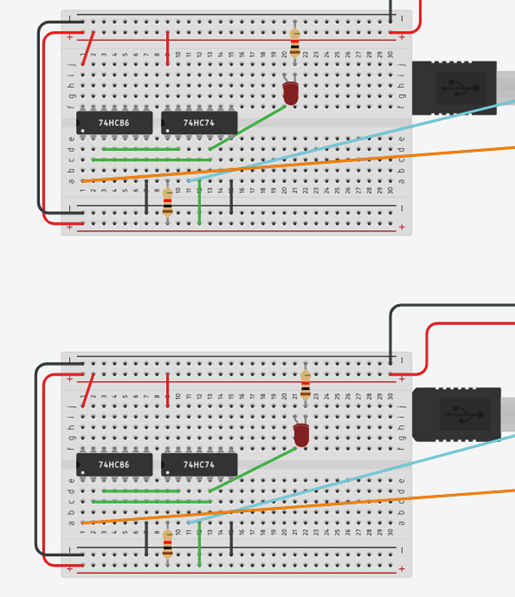
Implementation
Now that we understand what we want to do, it’s time to do it, this part is a lot complicated and I myself don’t understand it all too well. I could try to explain it but I think the best way to understand why it works is by watching Ben Aater's YouTube video about this topic Error detection So, what we are going to use is the 74HC74 and the 74HC86 as my D flip-flop and XOR gate, this is just cause that’s what is available in TinkerCad, but anything similar should do fine. What I did next was go to google and find the datasheets for these IC which explains how to set it up the only issue I had is the reset pin, which is apparently active low, which means that it should always be high. There is also a set pin which I didn’t know what to do with, so I just connected it to 5V and it works. I could have really done this using the Arduino itself, but I feel that by using the actual IC, you can understand it better. Now after transmission is complete, we should look at both the LED's and it should be in the same state. There is no difference in code.
I think this is the end of this project, we started by understanding the basics of communication, and then we saw how to solve the problem of synchronization, after which we implemented a basic parity checker. If you are interested in learning more about the verification then I suggest watching Ben Eater's videos on Check sums and CRC and its implementation. With this principle we can create many applications, a particular application which would be interesting is creating a morse code system. I shall implement a morse code station using these principles in my next project so stay tuned.


