

There has probably comes a time when you are using an Arduino and you wish you had more IO pins. The options to solve this are to either switch to an Arduino mega or use a I2C adaptor (for something like an LCD display). Another alternative would be to use two Arduino uno. The last option sound pretty easy but you would probably need the two of them to communicate or transfer data between them. Luckily, there are many ways to do this, but that got me thinking about how this communication works. I have used a few I2C devices like the DS3231 (real time clock) and other devices that communicated with I2C protocol. But all I did was import the wire library and just use those function, I never really understood how it worked fundamentally. There are 3 main communication protocols when it comes to Arduino, the I2C, SPI and uart. Instead of going through each method, let’s try coming up with our own communication protocol to understand what it means to transfer data. This project was essentially for me to understand how communication works between devices at a fundamental level. The goal is to take a binary number and give it to one Arduino and then send it to another other Arduino. So we have a transmission and receiving Arduino.
Data Transmission Principle
Now communication is essentially sending ones and zeros, and we can think of this as ON and OFF, I know this logic is repeated many times, so ill skip that part. First what we need to do is to get our message and convert it into ones and zeros. To send a one, we just turn the output high, we can do this easily with the digital write function in the Arduino. To send a zero we just turn the output low (basically do nothing) . For the transmission side, all we do is write the pin as high or low depending if it is one or zero. For the receiving side what we need to is to read if it is high or low. We can do this with the digital read function. If the port is high, we print a one, otherwise a zero.
Hardware
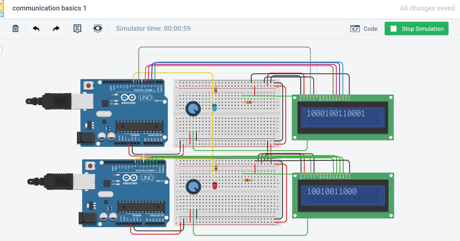
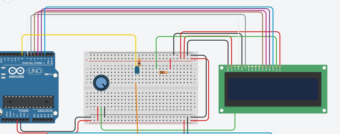
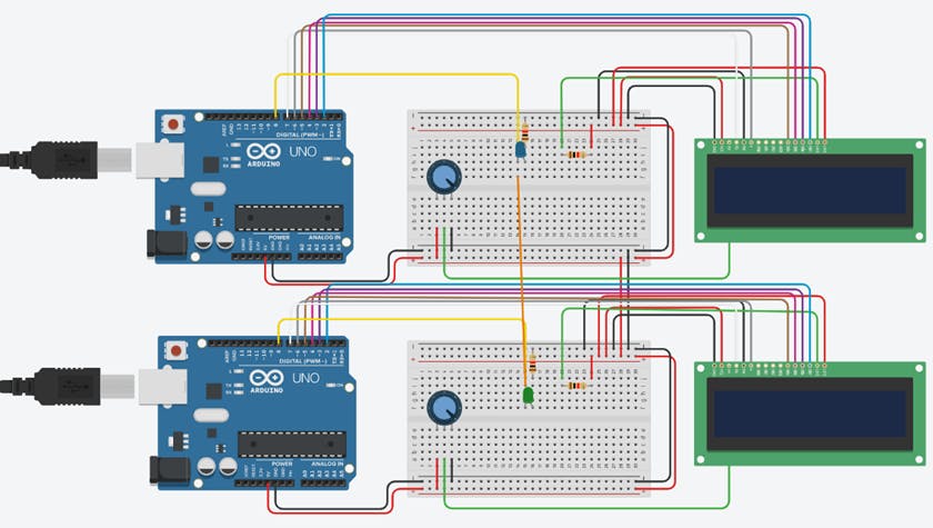
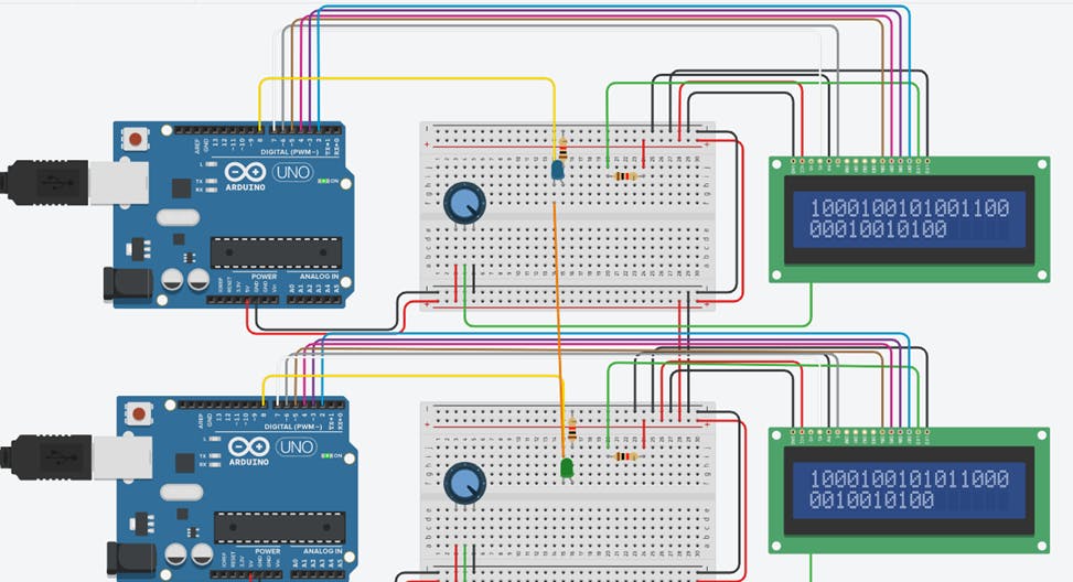
The first thing we need is two Arduinos, we also need these Arduinos to be as similar as possible, for reasons I’ll explain latter. I decided to use a simulation for this task, as that’s the only to get two identical Arduinos. It also means that we are testing out the theoretical aspect, and not taking into account the practical effects of resistance, and variation in computation time. But more importantly, we are not worried about starting both the Arduinos at the same time. I would be using tinkercad because it easy to use and works very well. It also has this amzing feaature where you can share the simulation on the blog (scroll to the bottom to see the simulation) So we first make the transmission station, there’s not much hardware just the LCD to display what character we are transmitting in real time.
The receiving station is the exact same assembly, and I connected both the systems by a single wire on port 8, I also added a LED here to make it easy to see when it is transmitting and when it is receiving.
Code
The harder code will be for the transmission so let’s start with that. First there is the LCD stuff which is very fundamental and I am just going to copy it off my previous project. Then I just define the message I want to send as a string. Here is where I ran into my first complication, ideally, I would like to use python and it wouldn’t be a string but a number, but then I realized I can’t iterate through it so then I used a character array which is pretty much the string and because I don’t use C++ or C, I don’t actually know what data type I’m using right now, but basically all I care about is that it is iterate able. Anyway, then I created a second string which will hold the current string I am sending. In the setup I just do the basic definitions and in the main loop I iterate through the length of the string and if it is a ’1’, I digital write the pin 8 (which is my transmission pin) high and if it equal to ’0’, I digital write low. Now all that is left is to print the character in the lcd after each transmission. Then we add a delay and the code is done. This delay actually has big consequences, it defines the speed of transmission. I will get to what it means latter, but right now all we are looking is transmitting data, and not about the speed of transmission.
//transmission
#include <LiquidCrystal.h>  // library for LCD
#define tx 8 // transmission pin as pin 8

LiquidCrystal lcd(7,6,5,4,3,2); //initializing LCD
char message[14]="10001001"; // this is the number I was to send
char m; //transmitting character
int mes=0;

void setup()
{
  pinMode(tx, OUTPUT); //setting the transmission pin as output
  lcd.begin(16,2); // initializing the LCD as 16x2
}

void loop()
{

  for (int i=0;i<strlen(message);i++){
    m=message[i];
    if (m=='1'){
      mes=1;}
    else if (m=='0'){
      mes=0;}
    digitalWrite(tx,mes);
    lcd.print(mes);
    delay(5000); //deal of 5000 ms= 5s
  }}
Now time for the receiving station, since this is just receiving data, there is not going to be much code in this. One thing I would recommend is to put labels in both your codes, so you know which one is transmitting and which one is receiving to make things easier. For the receiving station I’m not going to bother trying to figure out what the binary string means, I’m just interested in printing the string that I receive. Another important by subtle detail is that our delay time should be the same, which is the fundamental principle of synchronization in this method.
//receiving
#include <LiquidCrystal.h>
#define rx 8

LiquidCrystal lcd(7,6,5,4,3,2);
int mes;
void setup()
{
  pinMode(rx, INPUT);
  lcd.begin(16,2);
}

void loop()
{
mes=digitalRead(rx);
  lcd.print(mes);
  delay(5000);
  }
Okay so now it’s time to address all the errors, firstly I can’t get the backlight to work. It’s probably because I messed up the circuit connections, you know the ones I just copied, ya I messed up in coping my work, anyway who cares about the backlight, I’m good without it, it’s still visible. The other issue is that there is always an extra 0 at the start of the receiving system. I can see why it happens in the code, its because I start receiving even before the transmission starts so what I can try is just for the first pass I all not print the message, I know that’s sort of cheating, but it’s a work around and that’s good enough. The proper fix is creating synchronization and a clock which we will come to eventually. The revised code for receiving is as follows:
//receiving
#include <LiquidCrystal.h>
#define rx 8

LiquidCrystal lcd(7,6,5,4,3,2);
int mes;
int startval=0;
void setup()
{
  pinMode(rx, INPUT);
  lcd.begin(16,2);
}

void loop()
{

  mes=digitalRead(rx);
  if (startval==0){
    startval=1;}
  else{
    lcd.print(mes);}
  delay(5000);
  }
Results
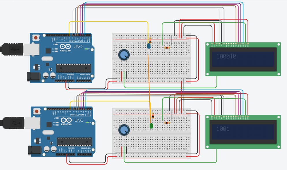
It works, but there is a lot to do to improve it, first the backlight needs to be fixed, which was a simple fix, I just swapped the anode and cathode, it’s something I always mix up. The next thing was the delay, 5000ms is way to slow, its waiting 5 seconds for each character, so I reduced it to 1000ms but it was still a little slow so I put as 100ms and it still worked, its probably only cause it’s a simulation and both Arduinos start at the same time, however had it been real hardware I would struggle to get both Arduinos to start at the same time. While I was at it I also cleaned up the code for the transmission.
 Seems all right? No there is actually a problem check the 13 character, it’s wrong, its cause of the difference in computations times, cause the transmission code takes more time to run than the receiving side and by the time I reach the 13 character these computation times add up and it messes up it from there, now I guess this is why they say you should always optimize your code. But however optimized the code is, it would still take more time on the transmission side that the receiving side so I have a better idea: make both equally bad, so I’m going to try to make the receiving code equally bad now, this involves computing stuff even if it doesn’t require it. This might sound stupid at first but actually it’s really smart, probably one of the best things I came up with. Work with me here, I just need both Arduinos to do the same amount of commutation, even I don’t need to use that computations, and this actually works, provided the Arduinos are identical and they both take the same amount of time to compute the same operation, which in a simulation is true. However, before I did this, I realized there would still be issues, firstly it would always require synchronization in the beginning. And only work if you’re sending a continuous message, it also won’t work if the Arduinos take different times to compute the same operation, which in real life is an actual problem. So, we need some other way of synchronization, some way for the Arduinos to know the time, we can use a clock for this. But a clock will take another wire, so if we need to send information across a single wire, with a low reliability then this method works, it is only susceptible to errors and can’t be used to non-continuous transmission, but this still has its uses.
Therefor if we don’t need to send data fast, we can use this method. By doing this project we have got a good idea of how communication works, now in my next project I’ll take it a little further by sending a clock also.
This project was inspired by a Ben eater YouTube video Reliable data transmission
The simulation can be see bellow:
Seems all right? No there is actually a problem check the 13 character, it’s wrong, its cause of the difference in computations times, cause the transmission code takes more time to run than the receiving side and by the time I reach the 13 character these computation times add up and it messes up it from there, now I guess this is why they say you should always optimize your code. But however optimized the code is, it would still take more time on the transmission side that the receiving side so I have a better idea: make both equally bad, so I’m going to try to make the receiving code equally bad now, this involves computing stuff even if it doesn’t require it. This might sound stupid at first but actually it’s really smart, probably one of the best things I came up with. Work with me here, I just need both Arduinos to do the same amount of commutation, even I don’t need to use that computations, and this actually works, provided the Arduinos are identical and they both take the same amount of time to compute the same operation, which in a simulation is true. However, before I did this, I realized there would still be issues, firstly it would always require synchronization in the beginning. And only work if you’re sending a continuous message, it also won’t work if the Arduinos take different times to compute the same operation, which in real life is an actual problem. So, we need some other way of synchronization, some way for the Arduinos to know the time, we can use a clock for this. But a clock will take another wire, so if we need to send information across a single wire, with a low reliability then this method works, it is only susceptible to errors and can’t be used to non-continuous transmission, but this still has its uses.
Therefor if we don’t need to send data fast, we can use this method. By doing this project we have got a good idea of how communication works, now in my next project I’ll take it a little further by sending a clock also.
This project was inspired by a Ben eater YouTube video Reliable data transmission
The simulation can be see bellow: