STM32 F4 - LED Blink and Setup

Hi, this blog is a way to keep all my projects in one place, while documenting the process along with all the problems that I encounter.
I have recently purchased a STM32 discovery board. I choose the STM32 F407VG DISC1. I purchased mine from evelta. They offer free shipping, cash on delivery (bellow Rs. 5000) and very fast delivery. I received mine within 5 days, shipped by FEDEX through ShipRocket. Their prices are reasonable and a wide range of products are available, so I suggest if you are looking to buy such a board you can check them out.
The board runs an ARM Cortex M4. The reason I went for the discovery board over the nucleo boards is the gyroscope and on-board LEDs. This is my first micro controller after the Arduino so I’m very excited to get started. The first thing to do with any microcontroller is to run a blink sketch on the board. So, in this project I will be providing a step-by-step process of what I did to get started. I would be using the Keil MDK to program the board.
Step 1
The first thing you need to get it a USB A to USB B wire. When you plug the wire into the USB jack on the board, you should see the LEDs blink. This is the factory uploaded code. If the user button is pressed once it runs the second program which uses the 3-axis gyroscope. If another USB micro-B is plugged in now, it will act as a USB mouse.
Step 2
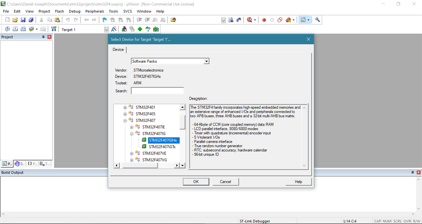
I then installed Keil MDK to program the board. After installing Keil MDK you would need to install the software pack for the specific board from keil. Then open up Keil MDK on your system and create a “new uVision project”. Select the respective board (make sure you have downloaded the software pack for your board.)
Step 3
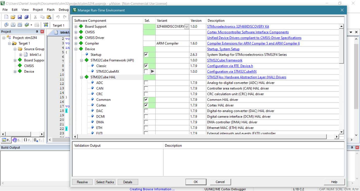
Then you get the run time environment window, this is where we are going to face a lot of trouble, it was a lot of trial and error but in the end, I found out what all packages I need to set up the board. It is important to note that you need to deselect packages, simply selecting all packages will not make it work, even if it sounds intuitive. There is a resolve button which is very useful, but it is not fool proof, I have written which of the following check boxes I ticked to successful build my project.
nothing is selected under “Board Support”
under “CMIS” make sure “CORE” is selected
nothing is selected under “CMSIS Driver”
nothing is selected under “Compiler”
“Device” is where you would face the most issues
Select “Startup”
Under “STM32Cube Framework(API)” make sure to select Classic
Under “STM32Cube HAL” make sure to select “Common”, ”Cortex”, “GPIO”, “PWR”, “RCC”
nothing is selected under “File System”, “Graphics”, “Graphics Display”, “Network” and “USB”
Make sure it isn’t showing any conflicts, if it is then click on resolve and try checking and unchecking some stuff until it works.
Step 4
Now we can create our project and start coding, make sure to create a new file and add it to the source group I am going to call my file blink and save it with a “.c” extension. I will first give you the whole code and then I will explain each part of the code at the end.
#include "stm32f4xx.h"
void configureLED(void);
void msDelay(uint32_t msTime);
int main(void)
{
    configureLED();
    msDelay(500);
    while (1)
    {
        GPIOD->ODR ^=(0xFUL<<12);
        msDelay(1000);
    }
}

void configureLED(void)
{
    RCC->AHB1ENR  |= (1UL<<3);
    GPIOD-> MODER &= ~(0xFFUL<<12*2);
    GPIOD-> MODER |= (0x55UL<<12*2);
}

void msDelay(uint32_t msTime)
{
    for (uint32_t i=0;i<msTime*4000;i++)
    {
        __NOP();
    }
}
Step 5
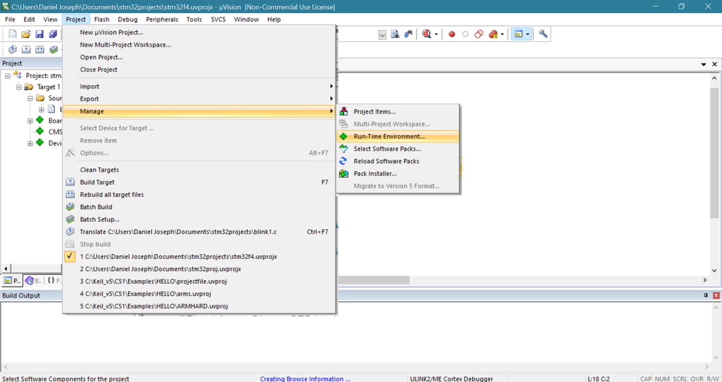
Now we can click Translate (Ctrl + F7) and check for errors. If there are no errors, we can procced to build the target (F7). When we build the target we might find errors with building the project, this is because of conflicts in the Run Time Environment, this errors are found by the Linker, while linking all the files, if you get such a error then go to PROJECT > Manage > Run-Time Environment and try checking and unchecking boxes, you can find out which packages are the problem by looking at the error message.
Step 6
If you have managed to successfully build your target all that is left to do is to plug in your board and download the sketch. Sounds like nothing can go wrong? Well, this is where I faced my biggest difficulties, I kept getting a error message saying “NO ULINK2/ME Device Found”. I assumed this was some problem with a windows driver that the board was not recognised so I installed the following package from the link.
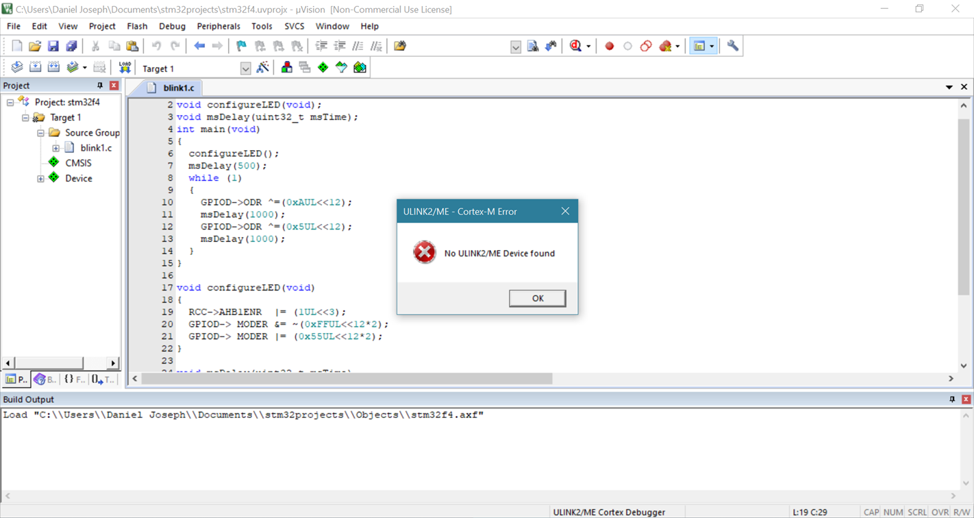
But it still didn’t work, so after some more googling I found out that I had to change my Debug option. Go to Flash > Configure Flash Tools > Debug and select “ST-Link Debugger” if you click on setting you should be able to see your device live.
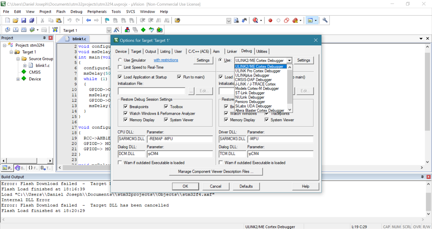
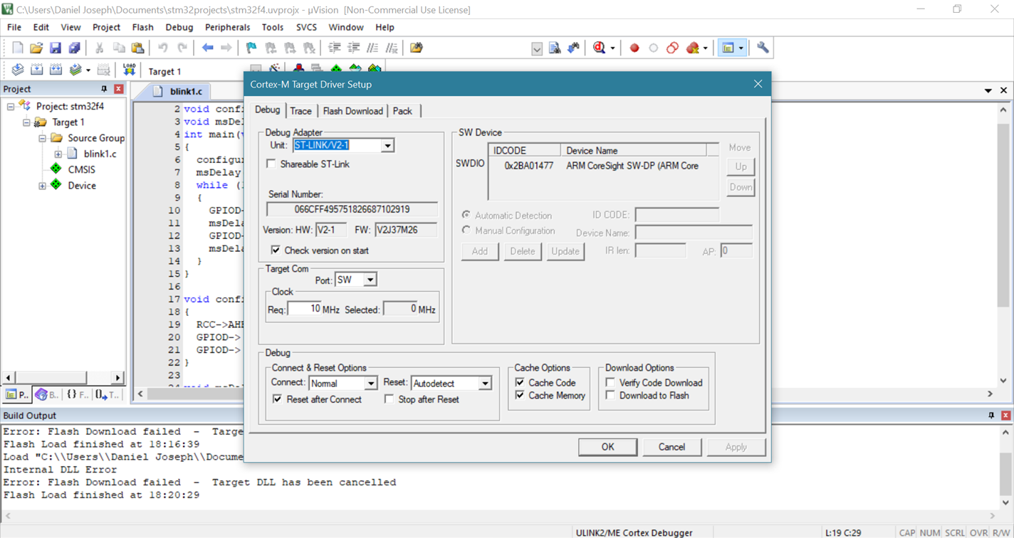
Now if you click on the download (F8) you should get a successful message like the following
“Load "C:\Users\Daniel Joseph\Documents\stm32projects\Objects\stm32f4.axf"
Erase Done.
Programming Done.
Verify OK.
Flash Load finished at 18:27:23”
Now press the Reset button on the board and your LED should be blinking successfully. If not, no big deal you learn a lot more by debugging that you would by coding, try again maybe what worked for me might not for you, try googling errors and try understanding where the error occurred and what could be changed to resolve the error.
Code Explanation
#include "stm32f4xx.h"
void configureLED(void);
void msDelay(uint32_t msTime);
Here the first line is something you will often see when writing c code, this line will include the stm32f4xx library file into the project. The second line is the function initialisation of configureLED which is a function which sets up the LED in output mode. The third line is again a function initialisation but this time for the msDelay function, this is used to create a delay. In c you have to initialise the function before you use them, hence we give just the initialisation in the beginning.
int main(void)
{
    configureLED();
    msDelay(500);
    while (1)
    {
        GPIOD->ODR ^=(0xFUL<<12);
        msDelay(1000);
    }
}
Here we start the main function, the first line is the start of the main. The first thing we do inside the main is all the configureLED function, which I’ll explain when I come to it, but all you need to know now is that we need to know is that before we use certain GPIO pins we need to set them up. After configuring the LED, we create a small delay for 50ms this isn’t too important and we could probably do without it but just to be on the safe side we create a small delay. We then start an infinite loop, the code inside this loop will run forever.
The next line is a little complicated but what it is doing is toggling the LED on and off after which we call a 1000ms delay, this delay can be increased or decreased depending on how you want your led to blink.
So, there is a register called the “odr” which stands for “output data register”.

Now we want to turn on and off the on-board LED, by looking at the hardware schematic of the board we can see that the on-board LED is connected to port D of the board, hence we use GPIOD had it been connected to port C we would use GPIOC.
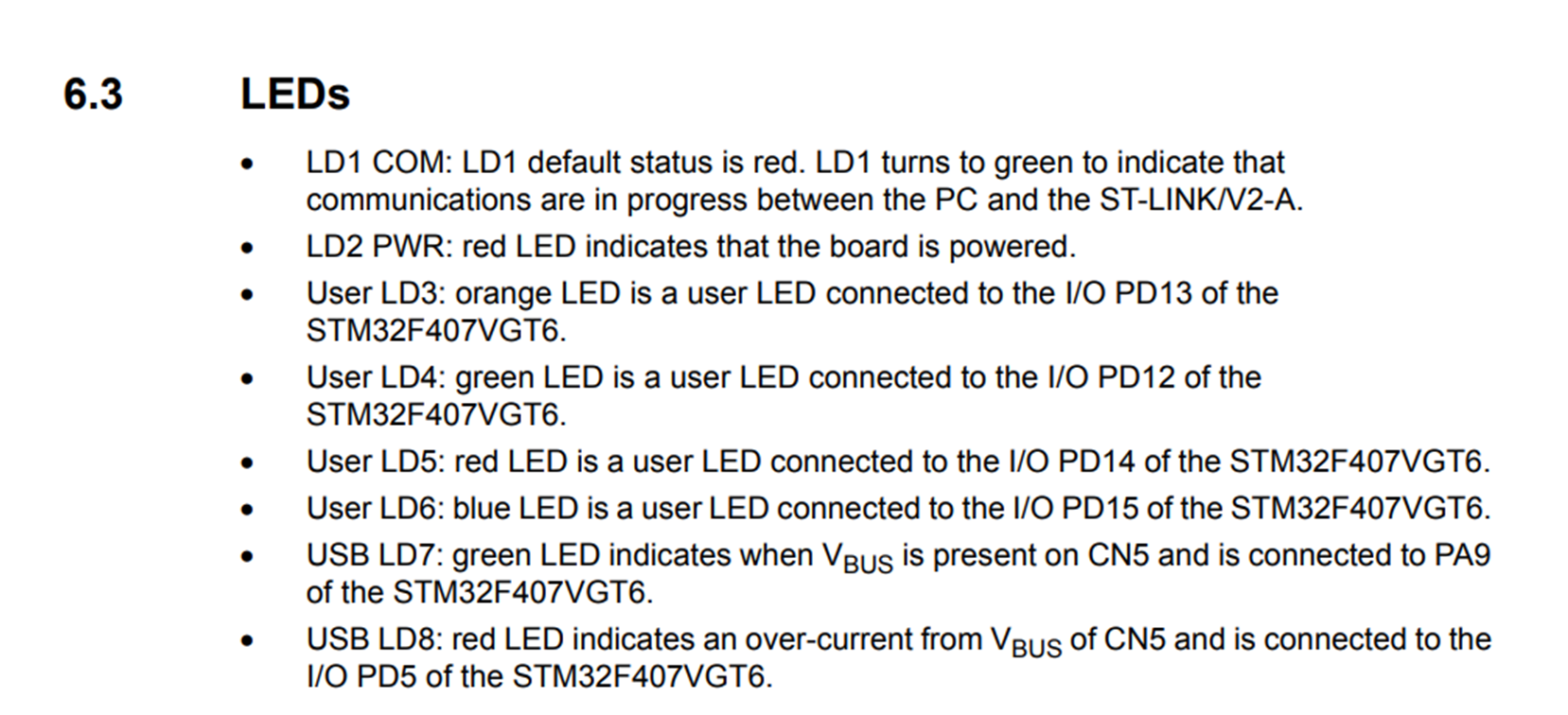
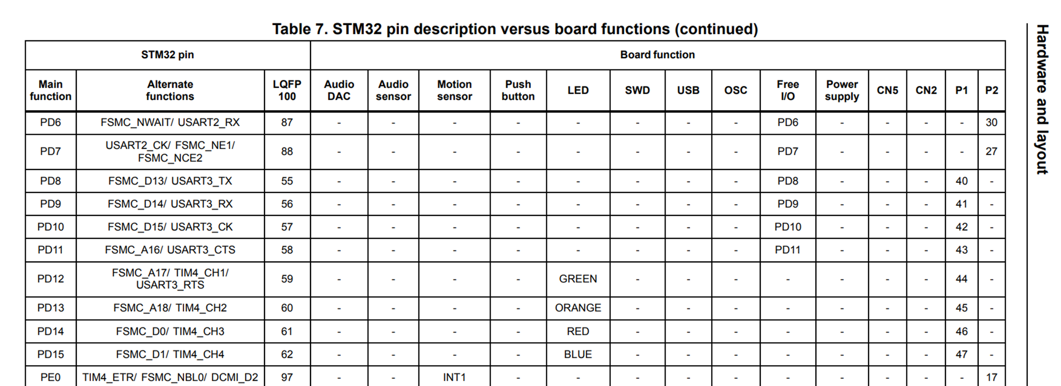
I have added the screen shots of datasheet of the Board, you can see that the 4 user LED is connected to PD12, PD13, PD14, PD15. That means port D pins 12, 13, 14, 15. So to turn on the LED we need to turn on these 4 pins (set them to one) and to turn the LED off we need to reset these 4 pins (set them to zero). So what we need to do is toggle these 4 bits, that is what we are doing in this one line.
GPIOD->ODR ^=(0xFUL<<12);
0xF is hexadecimal for 1111 in binary. These we can clarify with the calculator.
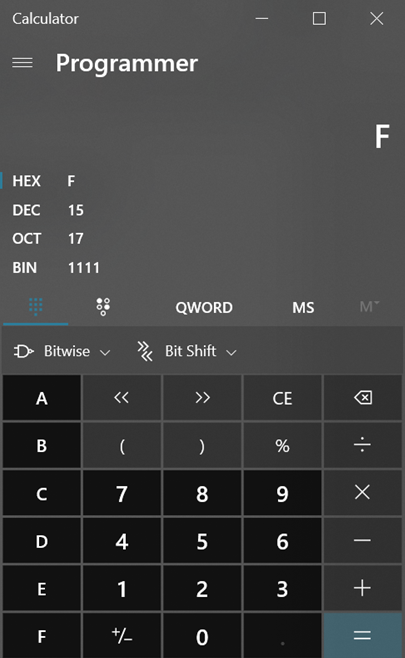
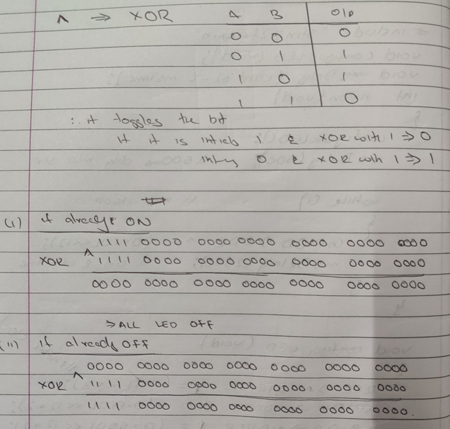
These 4 ones need to be moved to the 12, 13, 14, 15 bits of the register. We need all other bits should be zero. To do this we would use something called bit shifting. In essence what we want to do is set the 32-bit odr register to “1111 0000 0000 0000 0000 0000 0000 0000”. Instead of just typing so many zeros we can use bit shifting, that is get “1111” and shift it to the left 12 times. This is exactly what we are doing by typing “UL<<12”. I hope you understood this, it’s not easy to understand at first but you would get it with practice, there is also one more detail in this line which is the ^ before the equal to operator, this is the operator for XOR. What XOR does is essentially give a high output if either of the input is HIGH. This is used to toggle the bit (if it is already ON, then turn it OFF. If it is already OFF, then turn it ON)
If the bit is 1 (LED is on) then 1 XOR 1 gives 0. So, the bit is set to 0 and the LED is turned OFF.
If the bit is 0 (LED is off) then 0 XOR 1 gives 1. So, the bit is set to 1 and the LED is turned ON.
If you have still not understood I have tried doing it on paper if it helps.
void configureLED(void)
{
    RCC->AHB1ENR  |= (1UL<<3);
    GPIOD-> MODER &= ~(0xFFUL<<12*2);
    GPIOD-> MODER |= (0x55UL<<12*2);
}
Here we are defining our function to set up the LED and clock. The first line is to setup the clock. RCC stands for “Reset and Clock Control” and AHB1ENR is a register which is named because AHB stands for AH bus. inside the microprocessor, 1 is the index of the register, and then comes ENable Register. Going to the register data sheet we can find the following page.
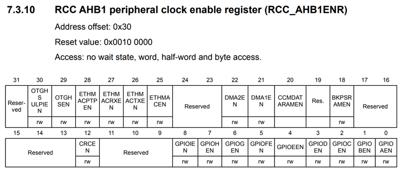
Bit 3 GPIODEN:
IO port D clock enable Set and cleared by software.
0: IO port D clock disabled
1: IO port D clock enabled
Therefore, as we are using port D, we need the clock for this port to be enabled. This is done by setting the 3rd bit to one. All we do is bit shift these 1 three times to the left to get “…00001000”.
The next 2 lines are related to the MODER register. The MODER is a GPIO register which is concerned with setting up the pin as an input or output. In an Arduino this two lines out simply be replaced with the following
pinMode(13, OUTPUT);
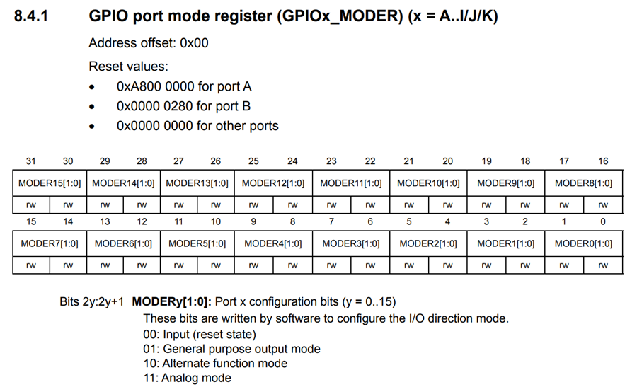
This is a 32-bit register with every two bits associate with a pin. Each pin has two bits therefore can have four possible modes (Input mode, Output mode, Alternate mode and Analog mode). We want to use the General purpose output mode which corresponds to 01. We are also only interested in MODER15, MODER14, MODER13, MODER12 which corresponds to bit 31, 30, 29, 28, 27, 26, 25, 24. We need to set MODER to “0101 0101 0000 0000 0000 0000 0000 0000”. This is exactly what we are achieving in the following two lines.
GPIOD-> MODER &= ~(0xFFUL<<12*2);
GPIOD-> MODER |= (0x55UL<<12*2);
0xFF in hexadecimal corresponds to “1111 1111” in binary and we left shit it 24 times (12*2=24) therefore we make bits 24 to 31 high and the other bits 0. This is then negated (~), that is one become zero and zero becomes one. This results in “0000 0000 1111 1111 1111 1111 1111 1111 1111 1111”. The “&” operator represents the AND function, which produces a HIGH output only if both inputs are HIGH. This is line is done so that the previous values of MODER stay the same and the most significant 8 bits are zero. This is done so that if there was any other pin set to output it will still be an output, in this program we are only using these 8 bits so its not a big deal. So, with this line we have achieved making the most significate 8 bits zero.
The next line sets the LED to output mode. 0x55 in hexadecimal corresponds to “0101 0101” this is then left shifted 24 times to get “0101 0101 0000 0000 0000 0000 0000 0000”. The “|” is the symbol for OR function so the previous value of the register is ORed with this new value. The OR function gives a HIGH output when either of the input is HIGH. Let x represent a unknow state (either 1 or 0). So previous state of MODER was “0000 0000 xxxx xxxx xxxx xxxx xxxx xxxx” and this is ORed with “0101 0101 0000 0000 0000 0000 0000 0000”
To give “0101 0101 xxxx xxxx xxxx xxxx xxxx xxxx” Therefore setting the LED to output mode and leaving the other bits as they were.
void msDelay(uint32_t msTime)
{
    for (uint32_t i=0;i<msTime*4000;i++)
    {
        __NOP();
    }
}
This function is a standard function to set up the delay function. “msTime” is a 32-bit integer hence we use uint32_t. There is not much to it, this is just the function we use to set up the delay, it is what can be used in most programs, that is to say it isn’t program specific.
There is one more important register that we didn’t use called the “OTYPER” register which chooses between push pull mode and open drain mode. By default, it is initialised to 0 and hence in push pull mode, had we needed to make it open drain we would have to set it to 1.


