Servo Motor
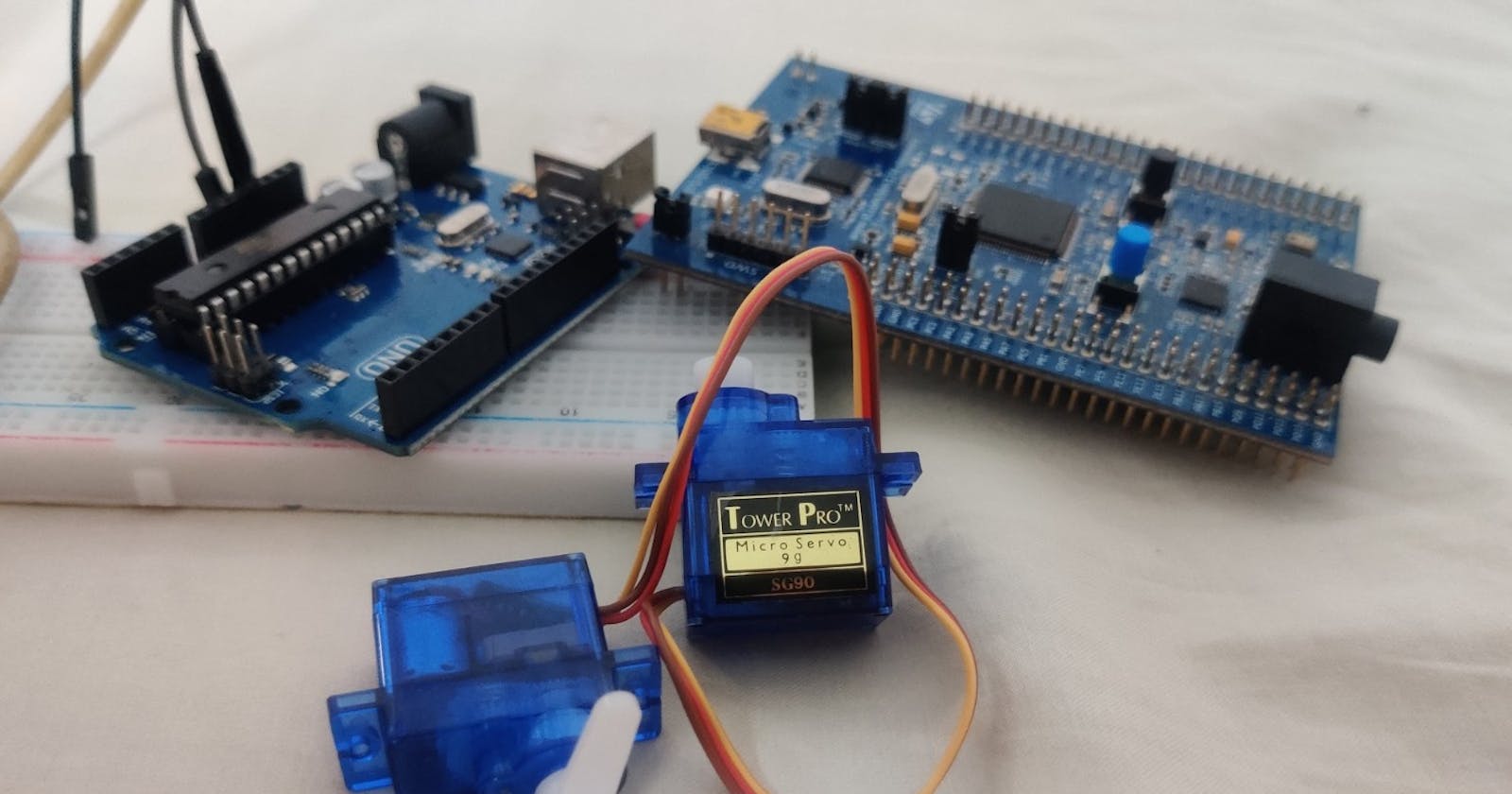
Interfacing Servo with Arduino Uno and STM 32 F407 Discovery


Today I am going to go somewhere I have been actively avoiding- Servo motors. I have had two 5V servo motors (which I got from Tomson’s Electronics) for a long time but I haven’t used it really because I don’t like PWM waves. I am not the biggest fan of timers and PWM because of the complexity. Today I have decided to stop running away and take the bull by the horns. Today we are going to interface the servo motor with an Arduino and STM32. In a following blog I am going to interface it with an FPGA. (Read it here)
Previous works
I actually have used the servo motors for a university project where I created a self-stabilizing spoon, but I just used Arduino libraries to implement it. In doing so I was able to remove all the complexities of actually using a servo. But if you want to have a look at the project then here is the final report our group made. However, I can justify using libraries over there as it was a very complicated project with an accelerometer and its calculations as well. You can find the code on my GitHub. I made sure to add a lot of comments so you understand what is going on.
If you follow this blog then you might know that I hate Arduino libraries. Well, I don’t hate it as such, but I just think that there is a place for them. Most people just implement a simple project with just a library and call it a day. Its great if you’re a beginner like I was when I created my IR Remote 1. There is a big difference between the IR Remote 2 and 1. Where I implemented the same thing without libraries. When using libraries, you don’t really understand how it works, there is a level of abstraction which takes away from understanding the fundamentals. The best example is actually the servo motors, I used the servo.h library and because of which I didn’t know that it used PWM, I didn’t know how to move the servo motor clockwise, all I did was tell the library to turn clockwise and the library did the PWM calculation for me.
Pulse Width Modulation
So back to the task at hand. We need to figure out what makes the servo motor turn, I said it involved PWM, but what exactly is it. First I’ll just give a small explanation of PWM. PWM stands for pulse width modulation. It is basically a square wave with different lengths. A PWM signal is just a signal which is on for some amount of time and off for the remaining time. The amount it is off and on is determined by the duty cycle. It is given by the formula:
Duty cycle = Ton / (Ton+Toff)
A 50% duty cycle means that the signal is on for half the cycle, and thus implying off for the other half. PWM may seem very simple and useless but is used everywhere. I was first introduced to PWM in power electronics, where it is used to control MOSFET’s and other Power transistors. You can learn a lot more in this amazing YouTube video. (skip till minute 7 if you are only interested in PWM)
What you may not know is that most analog signals might be PWM. See PWM, is a very good way to representing analog signals digitally. Analog signals are quite hard to send across digital systems, so they use PWM instead where the duty cycle represents the amplitude. PWM is a lot easier to implement compared to using an analog to digital converter to manage analog signals. PWM might also be more efficient when dealing with things like speed control. Instead of explaining the rest I am going to suggest you watch this video by great Scott which I personally enjoyed a lot after watching a second time .
Servo Motor Theory
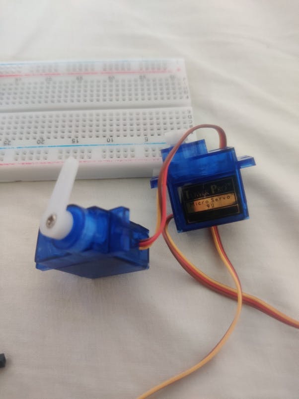
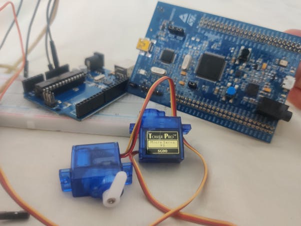
So, I kept going on and on about PWM but I haven’t really mentioned where it comes into the picture. Now I will explain how we control the motor. The servo motor I am using is a Tower pro SG90.
The servo motor enclosure might seem a quite small but there is quite a lot going on inside. If you take one apart (which I am not going to do) you will find that there is a lot of gears (providing the high torque), a motor as well as a circuit board and potentiometer. The potentiometer is just a feedback mechanism which gives data to the IC in the servo. Yes, the servo has its own dedicated IC inside its enclosure. It might be something like the IC KC5188 which is quite popular for this task. This is the motor driver IC, so what we have to do is to tell this IC what we want and the IC will do it for us. To communicate with the IC, we use PWM. Maybe one day, I will create my own servo which works on I2C. Actually, something like this exists, for this exact purpose. Well firstly when using many servo motors, it becomes quite hard to control each one, secondly the servo motors are normally controlled with timers which is quite a hassle. There does exist devices like the PCA9685 which connects to the I2C bus of the Arduino and will deal with the PWM, making our lives easier. However, I am not going to use those today as we are only using one servo.
To communicate with the IC its quite simple. The IC only really looks at the ON time of the signal. If the ON time is 1ms then the servo motor moves to the 0-degree position. If the ON time is 2ms then the servo motor moves to the 180-degree position. Any on time in between will result in a position between these two. The pulse length should be 20ms. Therefore, a 1m on time must be followed by a 19ms off time. Learn more from this video by Great Scot or this expertly made video by the drone bot workshop
We are going to be doing things differently. Instead of actually learning more about this signal in theory I thought we can see it in action. I thought we will use the Arduino and the servo.h library and program our servo to go to a certain pattern. We can then hook up my logic analyzer and have a look at the signal. This would be more interesting then actually learning the theory.
Arduino
I am going to start up my Arduino IDE which I haven’t opened in a while and kick up a simple example sketch as follows:
#include <Servo.h>
Servo ser;
void setup() {
  ser.attach(9);
  delay(100);
}
void loop() {
  ser.write(90);
  delay(2000);
  ser.write(0);
  delay(2000);
  ser.write(180);
  delay(2000);
}
Hardware
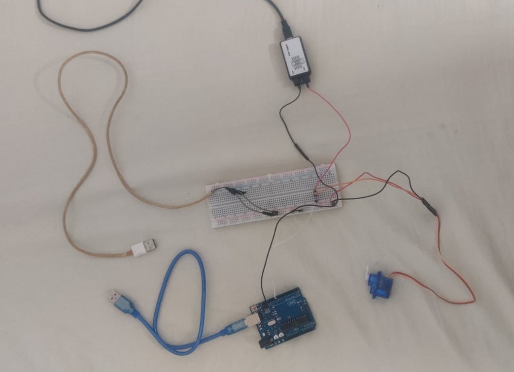
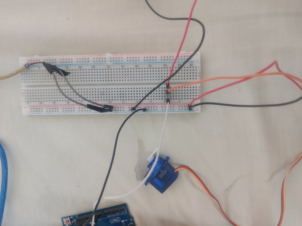
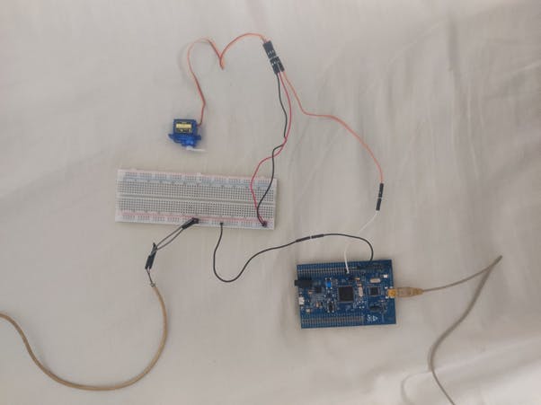
The servo has 3 wires, the power, ground and control. It is advised not to power the servo with the +5V of the microcontroller because of the higher current draw. The servo might also add a lot of noise to the signal or whatever, but I though why risk it and use another power supply. I had made a USB to male jumper cable in my externally powered board project which you can read here So I plugged the cable into my power bank and the positive jumper to the positive rail of the breadboard and the negative jumper to the negative rail. I then connect the positive of the servo to the positive rail of the breadboard and the negative rail to the negative of the servo. We also need to connect the ground of the Arduino to the negative of the breadboard. This is to have a common ground reference for the signal. Finally, I connected the control pin of the servo to the digital pin 9.
I tried it out and it worked exactly how I wanted it to. Now I connected up logic analyzer to the control pin of the servo and also referenced it to ground. We can now fire up the software and check out the waveform.
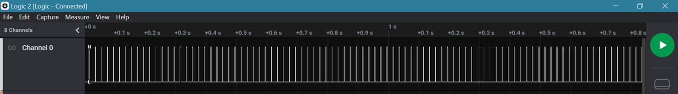
^ This is the waveform we seem to be getting, lets zoom in.
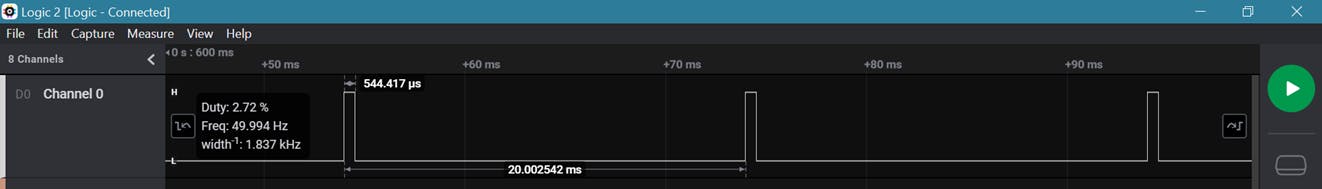
^ This is a signal with a on time of 544us and duty cycle of 2.73. This same signal is repeated 10 times after which it is followed by,
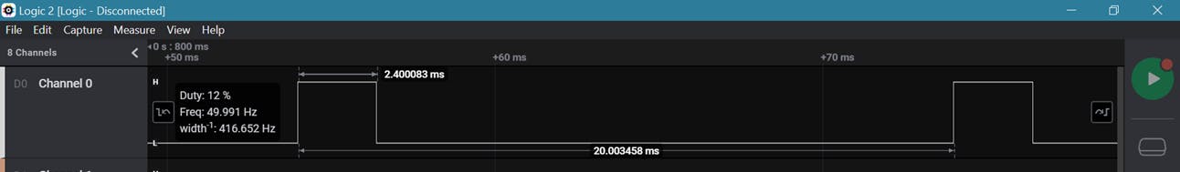
^ A signal with a on time of 2.4ms and duty cycle of 12. This signal is also repeated 10 times after which it is followed by,
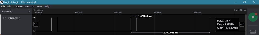
^ A signal with a on time of 1.4ms and duty cycle of 7.36. This is also repeated 10 times after which our cycle repeats.
After seeing the waveforms, it is very simple to do this without the library. The following code should do the same thing as the above Arduino code. Note this time there is no libraries involved.
void setup() {
  pinMode(9, OUTPUT);
}
void loop() {
  for (int i=0;i<10;i++)
  {
    digitalWrite(9,HIGH);
    delayMicroseconds(540);
    digitalWrite(9,LOW);
    delay(20);
  }
  delay(200);
  for (int i=0;i<10;i++)
  {
    digitalWrite(9,HIGH);
    delayMicroseconds(2000);
    digitalWrite(9,LOW);
    delay(18);
  }
  delay(200);
  for (int i=0;i<10;i++)
  {
    digitalWrite(9,HIGH);
    delayMicroseconds(1400);
    digitalWrite(9,LOW);
    delay(19);
  }
  delay(200);

}
The output is similar but not exact because we are using the Arduino IDE, this means that commands like digital Write take a little longer because there are a lot more instructions going on in the background. This isn’t such a big difference but it is the reason we aren’t getting exact 90 and 0 degrees and overshooting our 180-degree. This can be fine-tuned depending on your application but I think its fine.
STM 32
Now we can go ahead and implement the same thing on the ARM Cortex based board. Its not going to much different from the Arduino code. I have the option of using the hardware timers of the Discovery board but this would be a lot more tedious. I would rather just use software timer functions for now. Maybe in the future I would use the timers when I am using this in an application. For now, I am just going to use software timers and call it a day. I’m more excited to get to the FPGA, which is in the next blog.
Hardware
The connections are pretty similar, this time we don’t need the logic analyzer. I am using port A pin 0.
Code
Getting this code to work was a breeze. All I really had to do was bring out my delay microseconds and delay milliseconds functions which I made for my IR Remote project and implement the same Arduino code after initialing the ports.
If you feel like you need help with using timers then I would actually suggest an Arduino library. If you go on GitHub you can find the source code for the servo.h library This is a good reference to make your code from scratch.
#include "stm32f4xx.h"            // Include header file for the board

//Function prototype
void msDelay(uint32_t msTime);
void usDelay(uint32_t usTime)    ;
void configureLED(void);


int main(void)
{
    int i;
    configureLED();
    msDelay(500);
    while (1)
    {
        for (i=0;i<10;i++){
            GPIOA->ODR |= (0x1UL<<0);
            usDelay(540);
            GPIOA->ODR &= ~(0x1UL<<0);
            msDelay(20);
        }
        msDelay(200);

        for (i=0;i<10;i++){
            GPIOA->ODR |= (0x1UL<<0);
            usDelay(2010);
            GPIOA->ODR &= ~(0x1UL<<0);
            msDelay(18);
        }
        msDelay(200);

        for (i=0;i<10;i++){
            GPIOA->ODR |= (0x1UL<<0);
            usDelay(1500);
            GPIOA->ODR &= ~(0x1UL<<0);
            msDelay(19);
        }
        msDelay(200);
    }
}

void msDelay(uint32_t msTime)                //delay milli seconds
{
    //"For loop" takes 4 clock cycles to get executed. Clock frequency is 16MHz
    //16MHz/4=4MHz. If we want 1000ms (1second) delay, 4MHz/1000=4000, so we have to multiply by 4000 to get a delay of 1s
    for (uint32_t i=0;i<msTime*4000;i++)
    {
        __NOP();
    }
}

void usDelay(uint32_t usTime)                //delay micro second
{
    //"For loop" takes 4 clock cycles to get executed. Clock frequency is 16MHz
    //16MHz/4=4MHz. If we want 1000000us (1second) delay, 4MHz/1000000=4, so we have to multiply by 4 to get a delay of 1s
    for (uint32_t i=0;i<usTime*4;i++)
    {
        __NOP();
    }
}
void configureLED(void)
{
    RCC->AHB1ENR  |= (0x1UL<<0);        //port A clock enabled
    GPIOA->MODER |= (0x1UL<<0);            //setting bit 0 and 1 to "01" corresponding to output
}
Application
I extended this project by adding a push button and creating a prototype garage. You can find the video demonstration bellow. Here is the code for the STM 32
#include "stm32f4xx.h"            // Include header file for the board

//Function prototype
void open_sesseme(void);
void close_sesseme(void);
void msDelay(uint32_t msTime);
void usDelay(uint32_t usTime)    ;
void configureLED(void);


int main(void)
{
    uint32_t butt;
    configureLED();
    msDelay(500);
    while (1)
    {
        butt = ((GPIOB->IDR) & (0x1UL<<0));                // Reading the push button
        if (butt==0){
            open_sesseme();
        }
        else{
            close_sesseme();
        }
    }
}
void open_sesseme(void)                        // Function to open the gate
{
    int i;
    for (i=0;i<10;i++){
        GPIOA->ODR |= (0x1UL<<0);
        usDelay(540);
        GPIOA->ODR &= ~(0x1UL<<0);
        msDelay(20);
    }
    msDelay(200);
}

void close_sesseme(void)                    // Function to close the gate
{
    int i;
    for (i=0;i<10;i++){
        GPIOA->ODR |= (0x1UL<<0);
        usDelay(2010);
        GPIOA->ODR &= ~(0x1UL<<0);
        msDelay(18);
    }
    msDelay(200);

}
void msDelay(uint32_t msTime)                //delay milli seconds
{
    //"For loop" takes 4 clock cycles to get executed. Clock frequency is 16MHz
    //16MHz/4=4MHz. If we want 1000ms (1second) delay, 4MHz/1000=4000, so we have to multiply by 4000 to get a delay of 1s
    for (uint32_t i=0;i<msTime*4000;i++)
    {
        __NOP();
    }
}

void usDelay(uint32_t usTime)                //delay micro second
{
    //"For loop" takes 4 clock cycles to get executed. Clock frequency is 16MHz
    //16MHz/4=4MHz. If we want 1000000us (1second) delay, 4MHz/1000000=4, so we have to multiply by 4 to get a delay of 1s
    for (uint32_t i=0;i<usTime*4;i++)
    {
        __NOP();
    }
}
void configureLED(void)
{
    RCC->AHB1ENR  |= (0x1UL<<0);        //port A clock enabled
    RCC->AHB1ENR  |= (0x1UL<<1);        //port B clock enabled
    GPIOA->MODER |= (0x1UL<<0);            //setting bit 0 and 1 to "01" coreesponding to output

}
And here is the code for the Arduino.
int x=0;

void setup() {
  pinMode(9, OUTPUT);
  pinMode(8, INPUT);
}

void loop() {

  x = digitalRead(8);
  if (x==0){
    close_sesseme();
  }
  else{
    open_sesseme();
  }
}

void open_sesseme(){
  for (int i=0;i<10;i++)
  {
    digitalWrite(9,HIGH);
    delay(2);
    digitalWrite(9,LOW);
    delay(18);
  }
  delay(200);
}

void close_sesseme(){
  for (int i=0;i<10;i++)
  {
    digitalWrite(9,HIGH);
    delayMicroseconds(540);
    digitalWrite(9,LOW);
    delay(20);
  }
  delay(200);
}
Check out the rest of the project implemented on the FPGA here