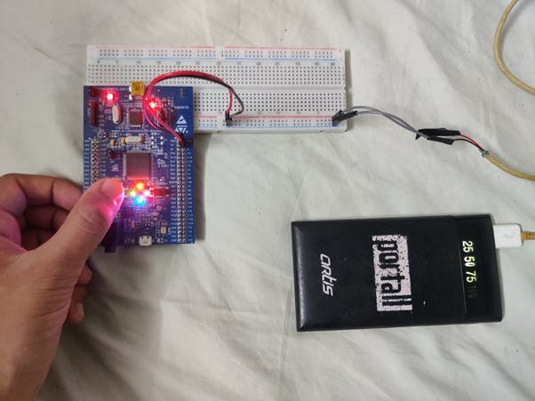


Hey! Today I’m going to implement a quick interrupt project. We are implementing a push button which triggers an interrupt. But we are not going to power our board over USB. We are going to create an external power supply and use it to power the circuit, instead of powering the circuit through the USB cable connected to the laptop.
Power supply
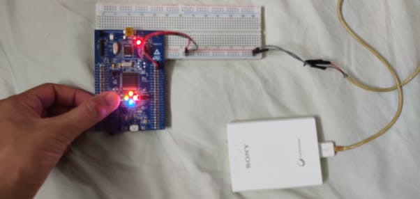
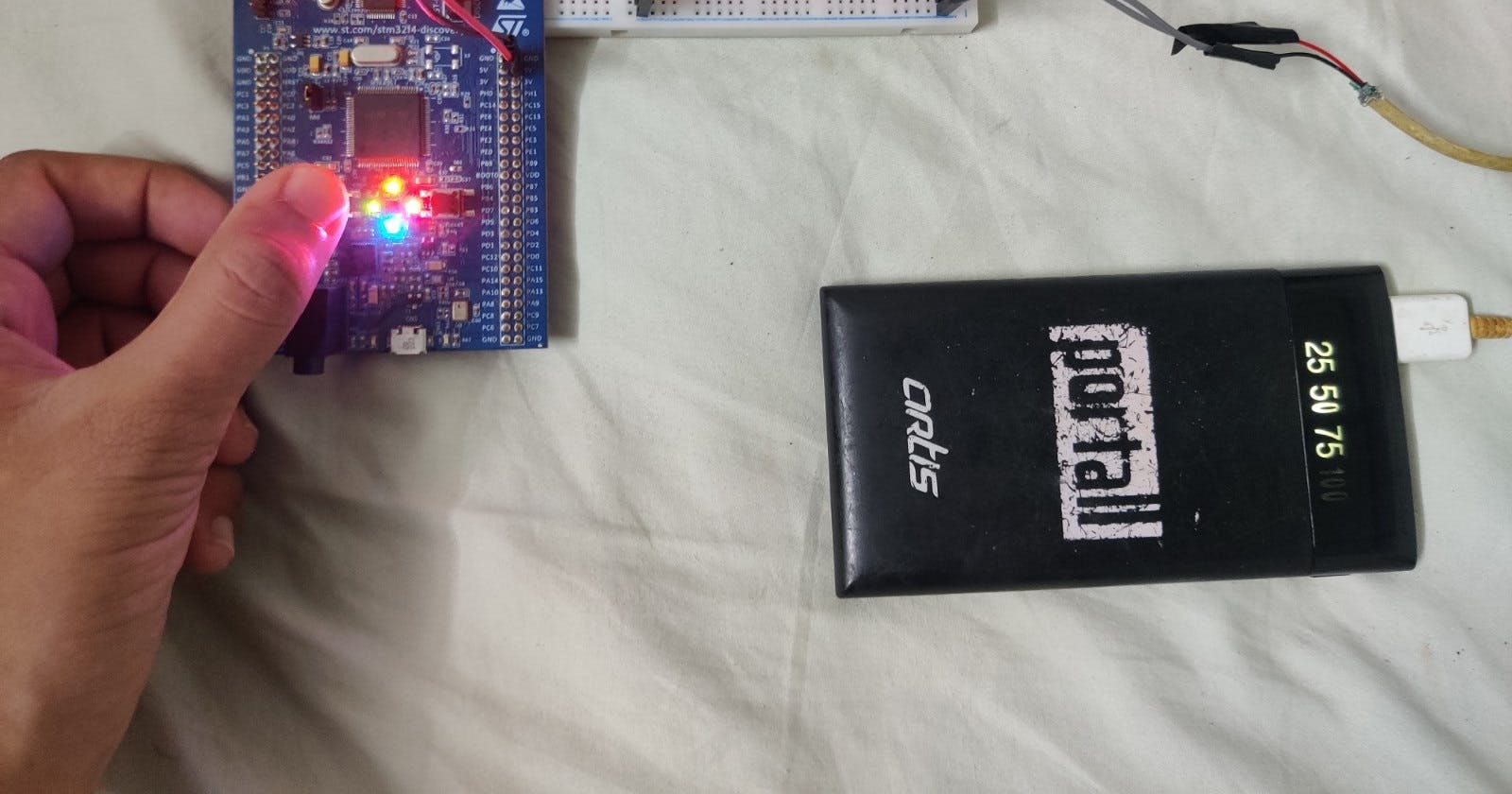
I want this project to be able to be movable. I don’t want to take my laptop with me everywhere just to power the circuit. This would have been very useful for my IR remote project, which you can read here I am going to be using a power bank. Just a regular cheap one I found lying around. These power banks are very useful as they output exact 5V which is required for the circuit.

Cable
I need a way to connect the power bank to the bread board. For this I will use a USB cable. I had many old cables lying around, so I took a look through them for a suitable cable.

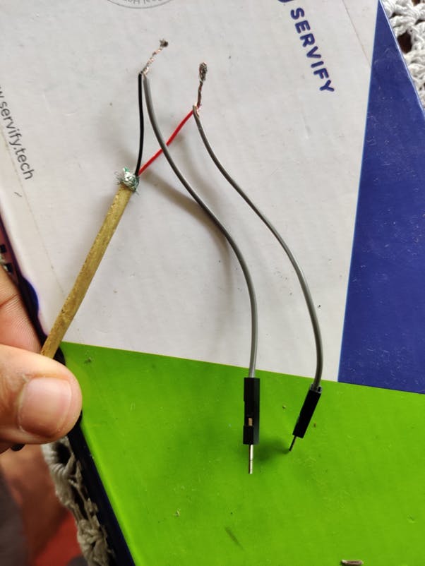
I took an old USB A to micro-USB cable, of which I have many lying around, and cut of the micro-USB side. You can use any able that has full size USB A on one end.

Depending on your cable you might find either 2 or 4 braids. Most of the cables would have 4 braids. These are the power, ground and D+ and D-. We only require the power and ground cable. You can go ahead cut of the 2 data wires. We now need to remove the insulation to expose the metal.
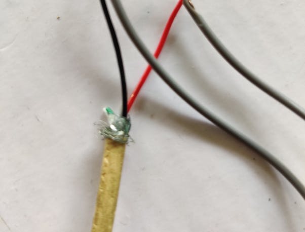
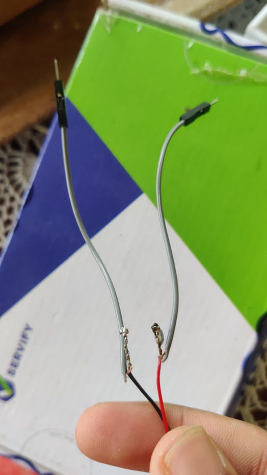
Now we need to connect this to the bread board. For this I’m going to use a male jumper. So, I’ll take a male-to-male jumper wire and cut it in half. Now I can strip the wire ends. Now twist one half of the jumper wire with the USB cable and repeat for the other wire.
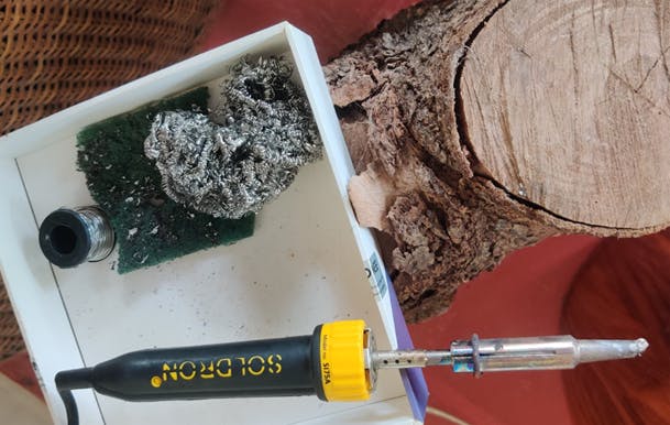
To make the connections more secure I am going to be soldering the wires. Soldering the wire will ensure a good mechanical and electrical connection.
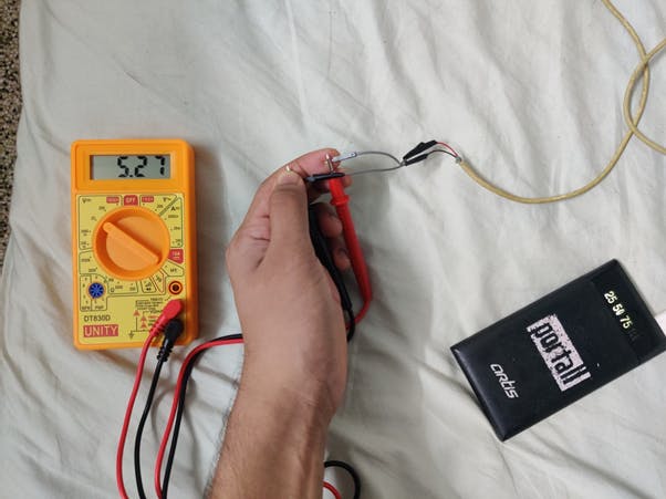
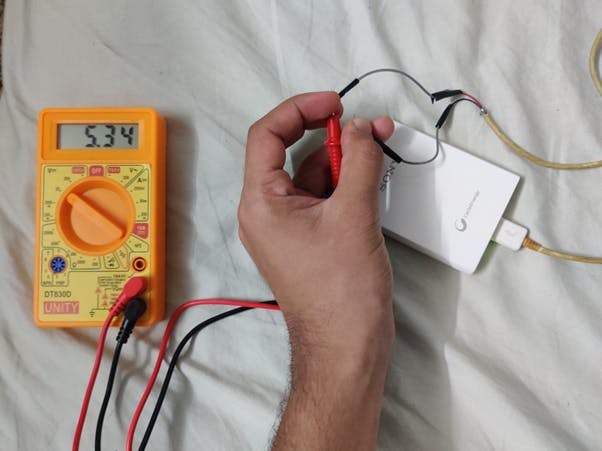
To finish it up ill just use some insulation tape to insulate the soler joints. This will prevent the wires from touching and creating a short circuit. To test our connections, we can connect the USB end to the power bank and use a multimeter to check the voltage on the ends of the cable. I measure exactly 5.27V for the first 10 seconds. If there is not current draw then the power bank goes into sleep mode, with the LED turning off and voltage reducing to 2.3V. Similar conditions were found for the other power bank.
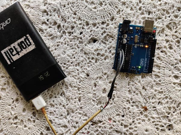
We can use this to power up different electronics. If you want to test it, I would suggest trying it out on an Arduino uno first. If it goes wrong, you would only destroy a Rs.200 board and not a Rs.2000 board. After trying it out on an Arduino I was pretty happy that it worked.
Interrupt
So firstly, an interrupt is an event that tells the micro controller to do a certain function. So, every time the interrupt is triggered, we jump to the ISR (Interrupt service routine) and perform a certain task. Here in the interrupt service routine, we will toggle the LED pin.
Code
#include "stm32f4xx.h"            // Include header file for the board

// Including prototypes for the functinos
void configureINT(void);
void configureLED(void);
void configurePB(void);
void EXTI0_IRQHandler(void);

int main(void)
{
    configureLED();                    // To configure the GPIO pins as output
    configurePB();                    // To configure the GPIO pins as input
    configureINT();                    // To configure the interupt registers
    while(1)
    {
    }
}
void EXTI0_IRQHandler(void)            // Interupt service routine that handels in the interupt
{
    EXTI->PR |= (1<<0);                        // To clear the intput flag
    GPIOD->ODR ^= (0xFFUL<<12);        // To toggle the LED

}

void configureINT(void)                    // To configure interupt and map it to the push button
{
    RCC->APB1ENR |= (1<<0);                // Enable clock for the Interupts
    EXTI->RTSR |=(1<<0);                    // To configure the interupts to occur on rissing edge
    EXTI->IMR |=(1<<0);                        // To remove the mask of the interupt (to enable interupts)
    NVIC->ISER[0] |= 1<<6;                // Nestered vector interupt controler. Tells what causes the interupt
}

void configureLED(void)                    // To configure GPIO port D as output
{
    RCC->AHB1ENR |=(1UL<<3);            // Enable clock for GPIO port D
    GPIOD->MODER &= ~(0xFFUL<<12*2);// To make sure all bits are 0
    GPIOD->MODER |= (0x55UL<<12*2);    // To make all pins as output
}

void configurePB(void)                    // To configure GRPIO port E as input
{
    RCC->AHB1ENR |=(0x1UL<<4);        // Enable clock for GPIO port E
}
The code is commented and self-explanatory.