


In a previous project I had interfaced the servo motors with microcontrollers (Arduino uno and STM 32 F07). If you haven’t read it yet go check it out first, as in this blog I won’t be explaining any of the theory. You can read the previous blog here In this project we are going to be interfacing the servo motors with the Altera Cyclone II FPGA.
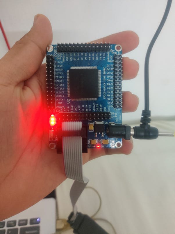
Altera Cyclone II FPGA
Now the main reason I started the previous project was to get a grasp with servo motors so that I would be able to use it with an FPGA. If you follow this blog, you will know that I recently got an Altera Cyclone II FPGA and have started working on it. Until now I have only implemented combinational logic on it. I thought it’s time to get some practice with sequential logic. The first sequential logical circuit I am going to do is a blinking LED, because jumping straight into PWM might be a little too complicated to get started. So, I came up with this Verilog code to blink the onboard LED of the FPGA. One thing to note while doing pin configurations is that, in this board the 50MHz clock is connected to PI_17. Other than that, everything else is just like my first FPGA project
Code
module PWM(CLK,OUT);
    input CLK;
    output OUT;
integer q = 1'b1;
supply0 z;
supply1 x;
always@(posedge CLK)
begin
q=q^1;
end
assign OUT = (q>0) ? x:z;
endmodule
The idea here is that I have a variable q. Every time the clock pulses I toggle the variable. This is done with the XOR gate. If q is 0, then I turn the LED off and if q is 1 then I turn it on. If I run this program on the FPGA you will first see no difference.
Output
But if you look carefully the LED 3 is dimmer than the rest. This is because the flipping is happing so fast, you can’t physically see it go off and on but the power to the LED is half. If you want to slow the process down then you can create a clock divider program. However, this will involve a lot of tedious calculations. Instead, we can use a counter in our code which is what we will do to create a PWM signal. Unfortunately, this will also involve some clock calculations.

^ Here is some rough calculations I did. I wrote the following code with those calculations and programmed by board. I then connected up my logic analyzer and looked at the waveform.
PWM
module PWM(CLK,OUT);
    input CLK;
    output OUT;

reg [24:0] counter = 0;

supply0 z;
supply1 x;

always@(posedge CLK)
begin

if (counter<100000)
    counter<=counter+1;
else
    counter<=0;

end
assign OUT  = (counter < 1000) ? x:z;
endmodule
The idea here is we use a counter and every time the positive edge of a clock occurs, we increment out counter and compare it to ON time and assign the output pin accordingly. I have just started writing code in Verilog so isn’t the most efficient.
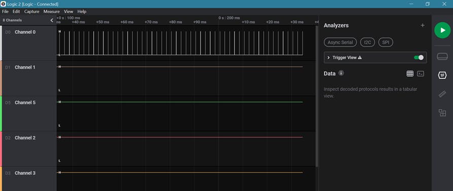
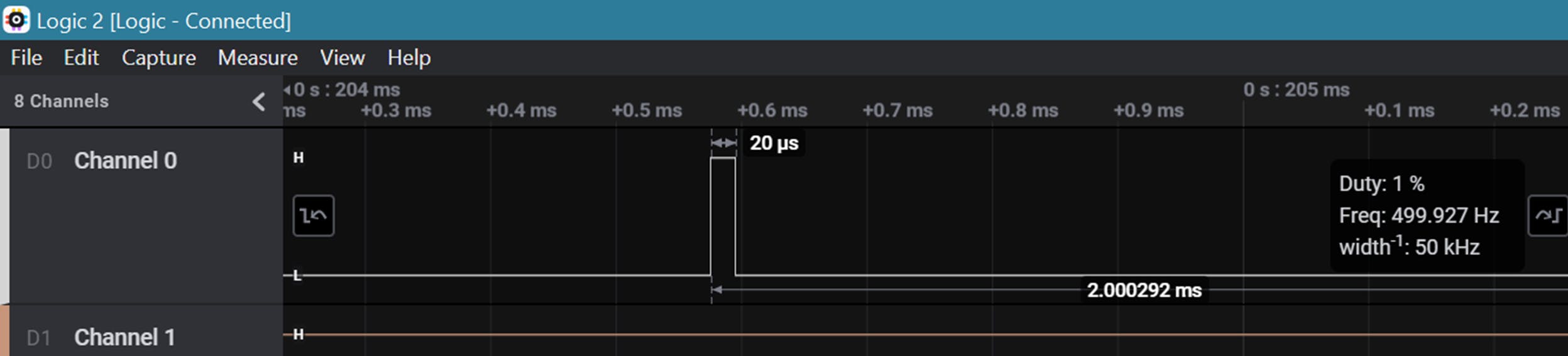
^ Here is the output waveform I got on the logic analyzer. If we zoom in, we see that our calculations were a bit off. However, by exampling our waveform we know exactly what to change.
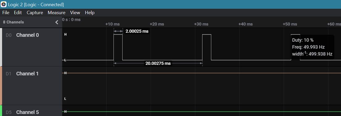
I added a zero to the assign statement and I was able to get the following waveform, which is exactly what I was looking for.
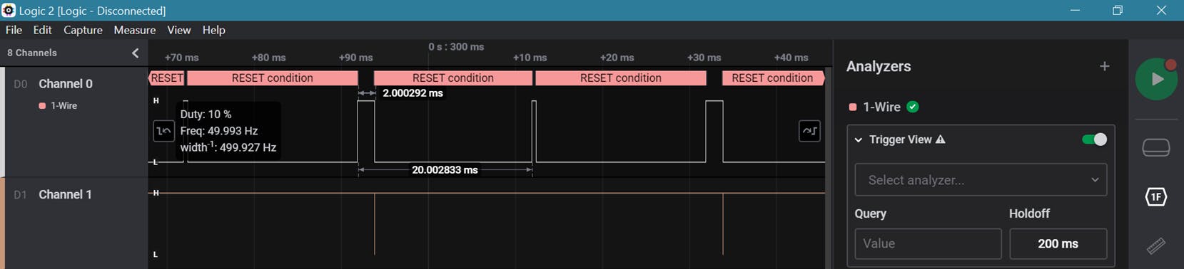
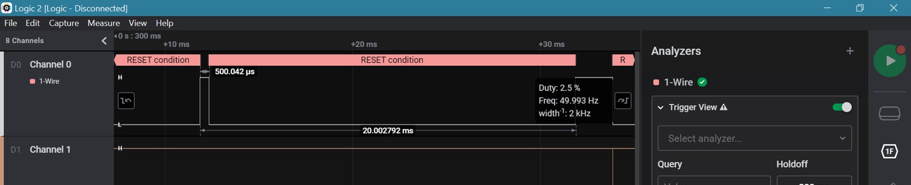
Now we can go ahead and add a second counter to enable our servo motor to sweep between two positions. I was able to come up with the following code to send a PWM signal of 10% duty cycle followed by a PWM signals of 2% duty cycle.
Servo Motor
module PWM(CLK,OUT);
    input CLK;
    output OUT;

integer q=1'b0;
integer temp=1'b0;

reg [24:0] counter1 = 0;
reg [24:0] counter2 = 0;

supply0 z;
supply1 x;

always@(posedge CLK)
begin
if (q>0)
begin
    if (counter1<1000000)
        begin
            counter1<=counter1+1;
        end
    else
        begin
            counter1<=0;
            q=q^1;
        end
    temp = (counter1 < 100000) ? 1'b1:1'b0;
end
else
    begin
        if (counter2<1000000)
            begin
                counter2<=counter2+1;
            end
        else
            begin
                counter2<=0;
                q=q^1;
            end
        temp = (counter2 < 25000) ? 1'b1:1'b0;
    end
end
assign OUT = (temp>0) ? x:z;
endmodule
Just to make sure we are getting what we expect I plugged in my logic analyzer to pin 4 and got the following waveforms.
Push Button
Our waveforms are good, we can now add our push button code. For this I’m going to add one more input which will be connect to the pin 8 of my board.
module PWM(CLK,IN,OUT);
    input CLK;
    input IN;
    output OUT;

integer temp=1'b0;                //output select

reg [24:0] counter1 = 0;
reg [24:0] counter2 = 0;

supply0 z;
supply1 x;

always@(posedge CLK)
begin
if (IN==1)
begin
    if (counter1<1000000)
        begin
            counter1<=counter1+1;
        end
    else
        begin
            counter1<=0;
        end
    temp  = (counter1 < 92000) ? 1'b1:1'b0;
end
else
    begin
        if (counter2<1000000)
            begin
                counter2<=counter2+1;
            end
        else
            begin
                counter2<=0;
            end
    temp  = (counter2 < 25000) ? 1'b1:1'b0;
    end
end
assign OUT = (temp>0) ? x:z;
endmodule
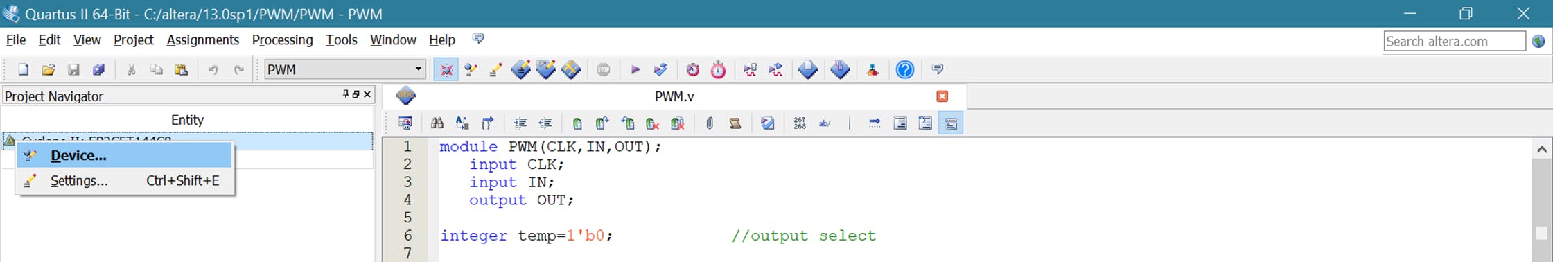
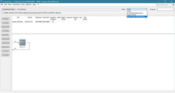
ASP
After testing my code an seeing that it works fine, I am going to program the memory of the board. This board can be programmed by JTAG, which will not store the code in its memory and therefore be lost once power is removed. Up until now I have only programmed this board with JTAG. There is a way for our program to stay in memory even after the power is removed. This is by programming out board over “Active Serial Programming” or ASP which will store the program in the EEPROM on the backside of the board. To do this first connect the USB blaster to the ASP connector. Then go to the left corner of Quartus and left click on your project and select device.
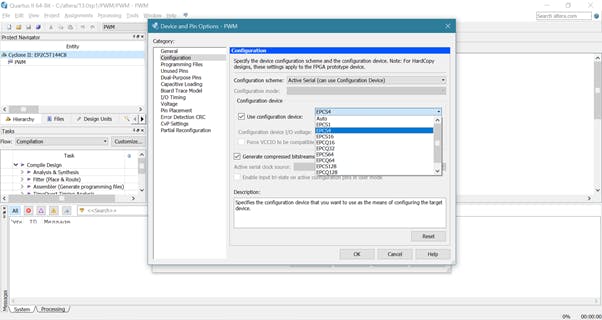
Then select “Device and Pin options” which will open up another window. Here we want to go into the configuration and change the option from “AUTO” to “EPCS4” which is the EEPROM on our board.
Now you can go to the programmer and select active serial programming instead of JTAG and start programming, now even after disconnection the USB blaster the code still remains on the board.
Smart Garage Door
Just for the sake of adding some spice, I spent some effort on presentation and I came up with a real-world application for the system we just implemented. The system is explained in my YouTube video which you can watch bellow. In the future I plan on using my IR remote to send a signal to a IR receiver (implemented on the FPGA) which will control the servo motor acting as a gate.
Reference: PWM in Verilog, Altera Cyclone II in VHDL