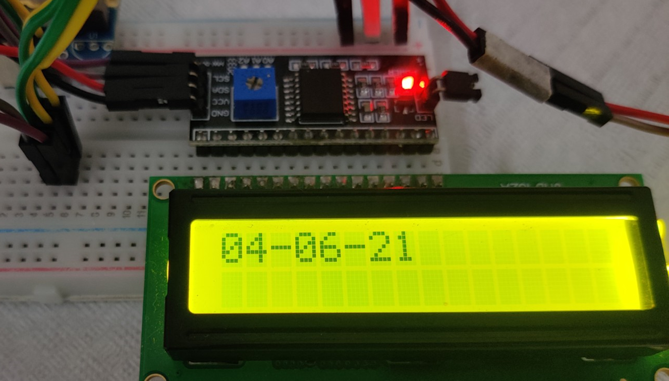
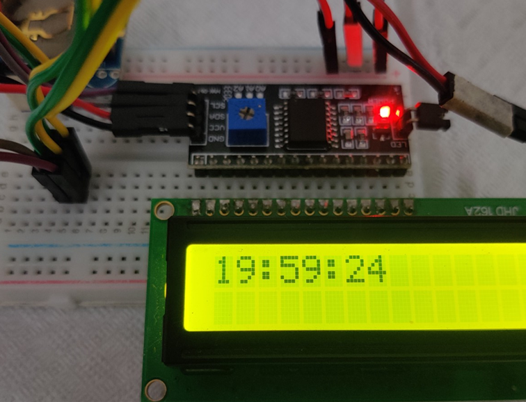
Hi, this blog is a way to keep all my projects in one place, while documenting the process along with all the problems that I encounter.
In theme of recent project, I would be continuing with interfacing I2C devices with my STM32 discovery board. Today I would like to interface the DS1307. It is a real time clock (RTC) which is very commonly used whenever time functionality is required. I am aware that the discovery board does have its own internal RTC, however that is for another project. Today we will interface the RTC module with the board using the I2C protocol and display the time and date on the LCD protocol through the I2C bus.
You can read my previous I2C project here: multiple I2C devices.
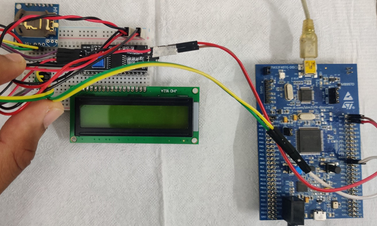
There is not much in terms on the physical connections, just connect the +5V from the board to the VCC of the RTC and I2C module as well the ground. The SDA and SCL connection must be given to both the peripherals from the pins PB6 and PB7 on the board.
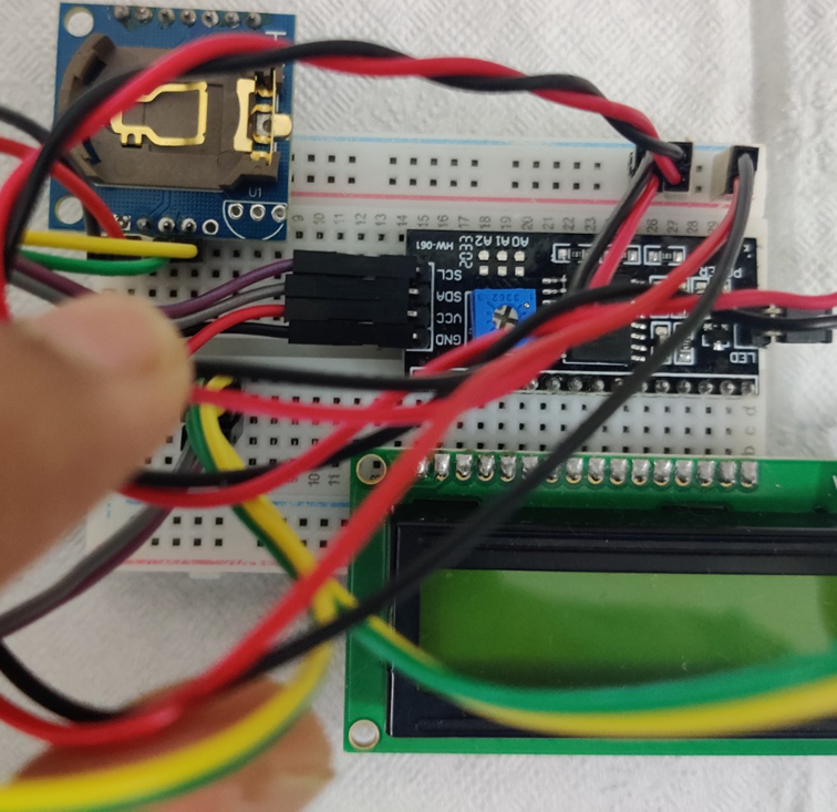
DS1307
The first step would be to actually interface the RTC with I2C. The first thing to do is to download the datasheet. You can find it here. In order to understand the working of the RTC we must thoroughly read the data sheet. According to me the most important two pages are pages 8 and 12. Even after reading the data sheet you might find some information is missing, this is where another very useful resource comes. See the Arduino community is a very big community with a lot of support, this means that there are many projects on many different devices available. There is a lot of libraries available too. What I do is go to the GitHub pages of one of these libraries and take a look at the source code for the library. For this project I referred to Paul Stroffregen’s DS1307RTC.cpp
While the code is quite different it is only the procedure that I refer. Here I looked at mostly the read and write functions. If the datasheet of the RTC was a bit more comprehensive I would not require to refer this code. However, the code is different and still a challenge to understand and replicate.
Binary Codded Decimal
The first thing that must be noted is that the module uses BCD (binary codded decimal). This might posses a challenge as it isn’t too common. However there are many tool to help you such as a online converter. I can tell you a hack that I used. On the windows calculator in programmer mode. If you want to convert 30 (base 10) to BCD. Just enter 30 as hexadecimal and you will get the BCD of 30 (base 10) as the binary of 30 (base 16).
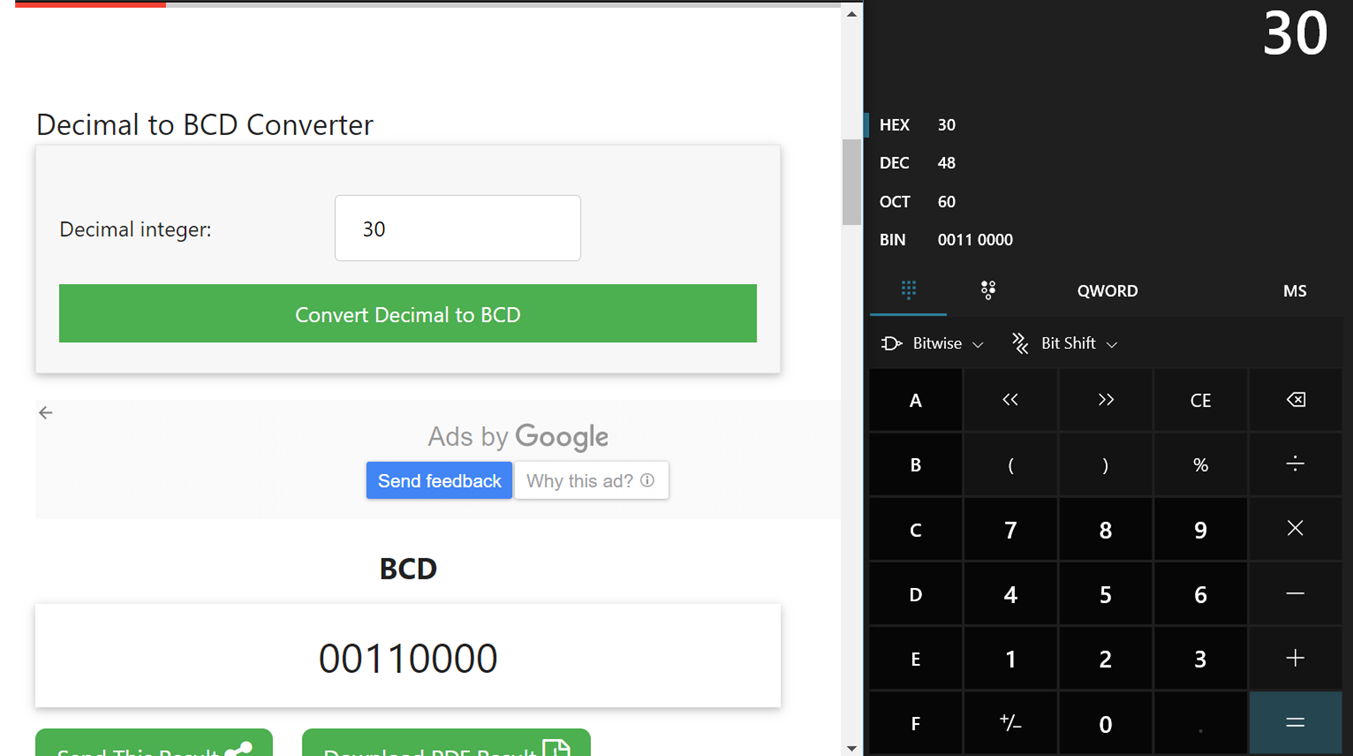
However, when we need to set the time and date, it would be very hard to enter it in BCD, so we can create a BCD to decimal function as well as a decimal to BCD function.
uint8_t decimal2bcd(uint8_t num){
    return ((num/10 * 16) + (num % 10));
}

uint8_t bcd2decimal(uint8_t num){
    return ((num/16 * 10) + (num % 16));
}
Setting Time and Date
The first thing we would need to do is to set the time and data on the RTC manually. There might be a way to get the system time and date from the compiler but that is a complicated process so I will just set it up manually in code.
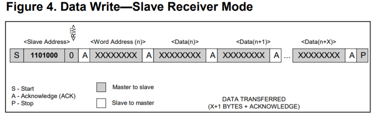
When we look at the page 8 of the datasheet, we can see the different registers on the module as well as its addresses. We can see that the address starts with 0x00 and goes till 0x06. It is also mentioned that register address is automatically incremented, that means after we write a value to the register 0x00, when we write the next value it will be written to 0x01. That means we can write 0x00 first and then write 7 sets of values for the 7 registers. There is one more trick here, we shouldn’t write the value of seconds first, this might create what is called the racing problem where before we set the other values the seconds value overflows creating problems, this could be the problem when we write the seconds as 58 or something. So, to avoid this problem I will write the seconds value last.
//function to set the time and date on RTC
void DS_setval(void){
    I2C_start();                                                        //send the start bit
    I2C_address(DS1307_ADDR);                                //send the addres of RTC
    I2C_write(0x00);                                                 //pointer at 00h register
    I2C_write(0x80);                                                 //stop the clock dont write seconds yet
    I2C_write(decimal2bcd(59));                         //minuits is 59
    I2C_write(decimal2bcd(19));                         //hour is 19
    I2C_write(decimal2bcd(3));                             //day of week is tuesday
    I2C_write(decimal2bcd(4));                             //date as 4
    I2C_write(decimal2bcd(6));                             //month as 6
    I2C_write(decimal2bcd(21));                         //year as 2021
    I2C_stop();                                                            //send the stop bit
    msDelay(1);
    I2C_start();                                                        //sending start bit again to set seconds
    I2C_address(DS1307_ADDR);                                //send the address of RTC
    I2C_write(0x00);                                                //pointer at 00h register
    I2C_write(decimal2bcd(16));                         //seconds as 16
    I2C_stop();                                                            //sent the stop bit
}
Reading Time and Date
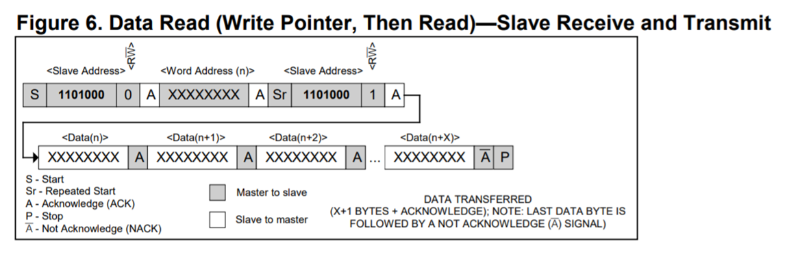
Now we can read the values of the registers from the RTC, this is done mostly with the I2C read function. Here we need to read the values continuously for 7 memory locations. We can follow the procedure from the datasheet by sending the repeated start bit. Here the “Word Address” would be 0x00.
//function to read values from the RTC
void DS_readval(void){
    uint8_t buf[7];                                                    //this buffer will store the 7 register values
    I2C_start();                                                        //sending start bit
    I2C_address(DS1307_ADDR);                                //sending the I2C address of RTC
    I2C_write(0x00);                                                //set the pointer to 0x00h register locatino
    I2C_start();                                                        //double start bit
    I2C_read(DS1307_ADDR+0x01, buf, 7);         //To read add one to I2C adress.
    I2C_stop();                                                            //send stop bit
    //set all the global variables
    sec=bcd2decimal(buf[0]&0x7F);                        //mask to remove the first bit
    min=bcd2decimal(buf[1]);
    hour=bcd2decimal(buf[2]);
    day=bcd2decimal(buf[3]);
    date=bcd2decimal(buf[4]);
    month=bcd2decimal(buf[5]);
    year=bcd2decimal(buf[6]);
}
Other Functions
I2C functions
The I2C functions involve the I2C_start, I2C_write, I2C_address, I2C_stop and I2C_read functions which I have used in previous projects.
LCD functions
The LCD functions include I2C_write4, I2C_write8, I2C_write4C, I2C_write8C and LCD_init functions which I have used in previous projects. A new function I have created is the LCD_code function, this function takes a number as a parameter and compares it to displays the corresponding character on the LCD.
Display Time and Date
To display the date and time I created two functions: LCD_display_time and LCD_display_date. What this function does is first isolate each digit (23 should become 2 and 3) and prints it in the corresponding format. For time I have used “hour:minuite:second” in 24 hour format and a colon “:” to separate it. For the date I have used “dd/mm/yy” with a forward slash “/” to separate it.
Interrupts
I am going to implement a functionality where I will display the time by default and if you want to see the data you can press the user button. I implemented this using interrupts as otherwise the button press may not get registered. The functions I used is rather common and in the interrupt service routine I just set a flag value.
Main function
The first thing to do in the main function is to configure all the GPIO and I2C registers as well as the interrupts. Then we can set the date and time and send the initial commands to the LCD. In the infinite loop we should first read the date and time. Then we can check if the flag is set. If it is set, we display the date and clear the flag. Most of the time the flag would not be set, then we should display the time. We must ensure to clear the LCD every time.
Code
#include "stm32f407xx.h" //include heder file for the board
//defining I2C adresses for different decives
#define DS1307_ADDR 0xd0 //I2C address of the RTC
#define LCD_ADDR 0x4E //I2C address of LCD
unsigned int temp=0; //temparory variable to clear the bit
uint8_t sec=0,min=0,hour=0,day=0,date=0,month=0,year=0; //global variables for all the registers
uint8_t d=0; //initializing varianble d
int flag=0; //flag for interupt
//pre initializing the functions
uint8_t bcd2decimal(uint8_t num);
uint8_t decimal2bcd(uint8_t num);
void interupt_init(void);
void EXTI0_IRQHandler( );
void DS_setval(void);
void DS_readval(void);
void LCD_display_time(void);
void LCD_display_date(void);
void configure_GPIOB(void);
void configure_I2C(void);
void msDelay(uint32_t msTime);
void I2C_start(void);
void I2C_write(uint8_t data);
void I2C_address(uint8_t Address);
void I2C_stop(void);
void I2C_read(uint8_t Address, uint8_t *buffer, uint8_t size);
void I2C_write4(uint8_t data);
void I2C_write8(uint8_t data);
void I2C_write4C(uint8_t data);
void I2C_write8C(uint8_t data);
void LCD_init(void);
void LCD_code(uint8_t num);
int main()
{
configure_GPIOB(); //to configure the GPIO pins PB6 and PB7
configure_I2C(); //to configure the I2C1 register
interupt_init(); //to configure the interupts
msDelay(100);
DS_setval(); //to set the time on the RTC
msDelay(100);
LCD_init(); //to set up the LCD, sending commands to the LCD, this would take a few seconds
while(1){
DS_readval(); //read values from the RTC
if (flag==1){ //if the push button is pressed
//to clear the contents on the screen
I2C_write4(0x01); //upper nibble
msDelay(37);
I2C_write8(0x01); //lower nibble
msDelay(37);
LCD_display_date(); //to display the date on the LCD
msDelay(1900); //dispaly the date for 2 seconds
flag=0;} //reset the flag value
else{ //if the push button is not pressed (default condition)
//to clear the contents on the screen
I2C_write4(0x01); //upper nibble
msDelay(37);
I2C_write8(0x01); //lower nibble
msDelay(37);
LCD_display_time(); //to display the time on the LCD
msDelay(900);
}
}
}
//function to convert decimal to BCD
uint8_t decimal2bcd(uint8_t num){
return ((num/10 * 16) + (num % 10));
}
//functino to convert BCD to decimal
uint8_t bcd2decimal(uint8_t num){
return ((num/16 * 10) + (num % 16));
}
//to configure the interupt
void interupt_init(void)
{
RCC->APB1ENR |= (1<<0); // enable PORTA clock
EXTI->RTSR |=(1<<0);
EXTI->IMR |=(1<<0);
NVIC->ISER[0] |= 1<<6;
}
//this function occures whenever interupt occurs
void EXTI0_IRQHandler( ){
EXTI->PR |= (1<<0);
flag=1; //set flag
}
//function to set the time and date on RTC
void DS_setval(void){
I2C_start(); //send the start bit
I2C_address(DS1307_ADDR); //send the addres of RTC
I2C_write(0x00); //pointer at 00h register
I2C_write(0x80); //stop the clock dont write seconds yet
I2C_write(decimal2bcd(59)); //minuits is 59
I2C_write(decimal2bcd(19)); //hour is 19
I2C_write(decimal2bcd(3)); //day of week is tuesday
I2C_write(decimal2bcd(4)); //date as 4
I2C_write(decimal2bcd(6)); //month as 6
I2C_write(decimal2bcd(21)); //year as 2021
I2C_stop(); //send the stop bit
msDelay(1);
I2C_start(); //sending start bit again to set seconds
I2C_address(DS1307_ADDR); //send the address of RTC
I2C_write(0x00); //pointer at 00h register
I2C_write(decimal2bcd(16)); //seconds as 16
I2C_stop(); //sent the stop bit
}
//function to read valus from the RTC
void DS_readval(void){
uint8_t buf[7]; //this buffer will store the 7 register values
I2C_start(); //sending start bit
I2C_address(DS1307_ADDR); //sending the I2C address of RTC
I2C_write(0x00); //set the pointer to 0x00h register locatino
I2C_start(); //double start bit
I2C_read(DS1307_ADDR+0x01, buf, 7); //To read add one to I2C adress.
I2C_stop(); //send stop bit
//set all the global variables
sec=bcd2decimal(buf[0]&0x7F); //mask to remove the first bit
min=bcd2decimal(buf[1]);
hour=bcd2decimal(buf[2]);
day=bcd2decimal(buf[3]);
date=bcd2decimal(buf[4]);
month=bcd2decimal(buf[5]);
year=bcd2decimal(buf[6]);
}
void LCD_display_time(void){
uint8_t hour_temp0, min_temp0, sec_temp0;
uint8_t hour_temp1, min_temp1, sec_temp1;
hour_temp0 = hour / 10;
hour_temp1 = hour % 10;
min_temp0 = min / 10;
min_temp1 = min % 10;
sec_temp0 = sec / 10;
sec_temp1 = sec % 10;
LCD_code(hour_temp0);
LCD_code(hour_temp1);
//to display the charecter ":"
I2C_write4C(0x3A); //upper nibble
msDelay(37);
I2C_write8C(0x3A); //lower nibble
msDelay(41);
LCD_code(min_temp0);
LCD_code(min_temp1);
//to display the charecter ":"
I2C_write4C(0x3A); //upper nibble
msDelay(37);
I2C_write8C(0x3A); //lower nibble
msDelay(41);
LCD_code(sec_temp0);
LCD_code(sec_temp1);
}
void LCD_display_date(void){
uint8_t date_temp0, month_temp0, year_temp0;
uint8_t date_temp1, month_temp1, year_temp1;
date_temp0 = date / 10;
date_temp1 = date % 10;
month_temp0 = month / 10;
month_temp1 = month % 10;
year_temp0 = year / 10;
year_temp1 = year % 10;
LCD_code(date_temp0);
LCD_code(date_temp1);
//to display the charecter "-"
I2C_write4C(0x2D); //upper nibble
msDelay(37);
I2C_write8C(0x2D); //lower nibble
msDelay(41);
LCD_code(month_temp0);
LCD_code(month_temp1);
//to display the charecter "-"
I2C_write4C(0x2D); //upper nibble
msDelay(37);
I2C_write8C(0x2D); //lower nibble
msDelay(41);
LCD_code(year_temp0);
LCD_code(year_temp1);
}
//function to congigure GPIO port b pin 6 and 7
void configure_GPIOB(void){
RCC->AHB1ENR |=(1UL<<1); //Enable clock for port B
GPIOB->MODER |=(2UL<<12); //PB6 to alternate function pin
GPIOB->MODER |=(2UL<<14); //PB7 to alternate function pin
GPIOB->PUPDR |=(0x5UL<<12); //set PB6 and 7 as pull up pins
GPIOB->OTYPER |=(0x3UL<<6); //Set PB6 and 7 as open drain
GPIOB->OSPEEDR |=(0xAUL<<12); //Set PB6 and 7 as high speed
GPIOB->AFR[0] |= (0x44<<24); //Set PB6 and 7 to alternate function 4
}
//function to configure I2C registers
void configure_I2C(void){
RCC->APB1ENR |=(1UL<<21); //Enable I2C clock
I2C1->CR1 |= (1UL<<15); //Reset I2C
I2C1->CR1 &= ~(1UL<<15); //set I2C
I2C1->CR2 |=(16UL<<0); //Set peripheral clock at 16MHz
I2C1->OAR1 |=(1UL<<14); //Should be set high
I2C1->CCR |=(0x50UL<<0); //Set SCL as 100KHz
I2C1->TRISE |=(17UL<<0); //Configure maximum rise time
I2C1->CR1 |= (1UL<<0); //Enable I2C
}
//function for sotware delay
void msDelay(uint32_t msTime){
//"For loop" takes 4 clock cycles to get executed. Clock frequency is 16MHz
//16MHz/4=4MHz. If we want 1000ms (1second) delay, 4MHz/1000=4000, so we have to multiply by 4000 to get a delay of 1s
for (uint32_t i=0;i<msTime*4000;i++){
__NOP();
}
}
//function to set I2C start bit
void I2C_start(void){
I2C1->CR1 |= (1<<10); //Enable the ACK Bit
I2C1->CR1 |= (1<<8); //Send the start bit
while (!(I2C1->SR1 & (1<<0))); //Wait for SB bit to set
}
//function to write data
void I2C_write(uint8_t data){
while (!(I2C1->SR1 & (1<<7))); //Wait till TX buffer is empty
I2C1->DR = data; //Write data to I2C slave
while (!(I2C1->SR1 & (1<<2))); //Wait till Byte transfer is completed
}
//function to send I2C adress
void I2C_address(uint8_t Address){
I2C1->DR = Address; //send the slave address
while (!(I2C1->SR1 & (1<<1))); // wait for ADDR bit to set
temp = I2C1->SR1 | I2C1->SR2; //read SR1 and SR2 to clear the ADDR bit
}
//function to send the stop bit
void I2C_stop(void){
I2C1->CR1 |= (1<<9); //Stop I2C
}
//function to read from I2C device
void I2C_read (uint8_t Address, uint8_t *buffer, uint8_t size)
{
int remaining = size;
if (size == 1)
{
I2C1->DR = Address; //send the address
while (!(I2C1->SR1 & (1<<1))); //wait for ADDR bit to set
I2C1->CR1 &= ~(1<<10); //clear the ACK bit
temp = I2C1->SR1 | I2C1->SR2; //read SR1 and SR2 to clear the ADDR bit.... EV6 condition
while (!(I2C1->SR1 & (1<<6))); //wait for RxNE to set
buffer[size-remaining] = I2C1->DR; //Read the data from the DATA REGISTER
}
else
{
I2C1->DR = Address; //send the address
while (!(I2C1->SR1 & (1<<1))); //wait for ADDR bit to set
temp = I2C1->SR1 | I2C1->SR2; //read SR1 and SR2 to clear the ADDR bit
while (remaining>2)
{
while (!(I2C1->SR1 & (1<<6))); //wait for RxNE to set
buffer[size-remaining] = I2C1->DR; //copy the data into the buffer
I2C1->CR1 |= 1<<10; //Set the ACK bit to Acknowledge the data received
remaining--;
}
while (!(I2C1->SR1 & (1<<6))); //wait for RxNE to set
buffer[size-remaining] = I2C1->DR;
I2C1->CR1 &= ~(1<<10); //clear the ACK bit
I2C1->CR1 |= (1<<9); //stop I2C
remaining--;
while (!(I2C1->SR1 & (1<<6))); //wait for RxNE to set
buffer[size-remaining] = I2C1->DR; //copy the data into the buffer
}
}
void I2C_write4(uint8_t data){ //to send upper four bit for commands
d=0; //reset value for d
d |= (data & 0xF0); //fto select only the upper nibble
d |= 1<<2; //to set the enable bit
d |= 1<<3; //to set the backlight
I2C_start(); //send the start bit
I2C_address(LCD_ADDR); //send the I2C address
I2C_write(d); //send the data
msDelay(1); //wait for 1ms
d &= ~(1<<2); //set the enable bit low
I2C_write(d); //send the same data but without enable bit to latch the data
I2C_stop(); //send the stop bit
}
void I2C_write8(uint8_t data){ //to send lower four bit for commands
d=0;
d |= ((data & 0x0F)<<4); //to select only the lower nibble
d |= 1<<2;
d |= 1<<3;
I2C_start();
I2C_address(LCD_ADDR);
I2C_write(d);
msDelay(1);
d &= ~(1<<2);
I2C_write(d);
I2C_stop();
}
void I2C_write4C(uint8_t data){ //to send upper four bits for data
d=0;
d |= (data & 0xF0); //to select only the upper nibble
d |= 1<<2;
d |= 1<<0; //to select the data register not the command
d |= 1<<3;
I2C_start();
I2C_address(LCD_ADDR);
I2C_write(d);
msDelay(1);
d &= ~(1<<2);
I2C_write(d);
I2C_stop();
}
void I2C_write8C(uint8_t data){ //to send the lower four bits for data
d=0;
d |= ((data & 0x0F)<<4); //to select only the lower nibble
d |= 1<<2;
d |= 1<<0; //to select data register not command register
d |= 1<<3;
I2C_start();
I2C_address(LCD_ADDR);
I2C_write(d);
msDelay(1);
d &= ~(1<<2);
I2C_write(d);
I2C_stop();
}
//to send the initial commands to the LCD
void LCD_init(void){
//following commands reffered for libray
I2C_write4(0x30); //to clear the screen
msDelay(4200);
I2C_write4(0x30); //to clear the screen
msDelay(150);
I2C_write4(0x30); //to clear the screen
msDelay(37);
I2C_write4(0x20); //to turn on the screen
msDelay(37);
//to set LCD to 4 bit mode and 2 lines, 5x8 font
I2C_write4(0x28); //upper nibble
msDelay(37);
I2C_write8(0x28); //lower nibble
msDelay(37);
//to turn the display on with blinking curesor
I2C_write4(0x0C); //upper nibble
msDelay(37);
I2C_write8(0x0C); //lower nibble
msDelay(37);
//to clear the contents on the screen
I2C_write4(0x01); //upper nibble
msDelay(37);
I2C_write8(0x01); //lower nibble
msDelay(1600);
//to set LCD to write from left to right
I2C_write4(0x06); //upper nibble
msDelay(37);
I2C_write8(0x06); //lower nibble
msDelay(37);
}
//function to match the number and display it
void LCD_code(uint8_t num){
if (num==0){
//to display the charecter "0"
I2C_write4C(0x30); //upper nibble
msDelay(37);
I2C_write8C(0x30); //lower nibble
msDelay(41);}
else if (num==1){
//to display the charecter "1"
I2C_write4C(0x31); //upper nibble
msDelay(37);
I2C_write8C(0x31); //lower nibble
msDelay(41);}
else if (num==2){
//to display the charecter "2"
I2C_write4C(0x32); //upper nibble
msDelay(37);
I2C_write8C(0x32); //lower nibble
msDelay(41);}
else if (num==3){
//to display the charecter "3"
I2C_write4C(0x33); //upper nibble
msDelay(37);
I2C_write8C(0x33); //lower nibble
msDelay(41);}
else if (num==4){
//to display the charecter "4"
I2C_write4C(0x34); //upper nibble
msDelay(37);
I2C_write8C(0x34); //lower nibble
msDelay(41);}
else if (num==5){
//to display the charecter "5"
I2C_write4C(0x35); //upper nibble
msDelay(37);
I2C_write8C(0x35); //lower nibble
msDelay(41);}
else if (num==6){
//to display the charecter "6"
I2C_write4C(0x36); //upper nibble
msDelay(37);
I2C_write8C(0x36); //lower nibble
msDelay(41);}
else if (num==7){
//to display the charecter "7"
I2C_write4C(0x37); //upper nibble
msDelay(37);
I2C_write8C(0x37); //lower nibble
msDelay(41);}
else if (num==8){
//to display the charecter "8"
I2C_write4C(0x38); //upper nibble
msDelay(37);
I2C_write8C(0x38); //lower nibble
msDelay(41);}
else if (num==9){
//to display the charecter "9"
I2C_write4C(0x39); //upper nibble
msDelay(37);
I2C_write8C(0x39); //lower nibble
msDelay(41);}
else{ //if unrecognised charecter display "#"
//to display the charecter "#"
I2C_write4C(0x23); //upper nibble
msDelay(37);
I2C_write8C(0x23); //lower nibble
msDelay(41);}
}
Output