Altera Cyclone II
Getting started with the Cyclone II EP2C5T144C8N FPGA

Hi, this blog is a way to keep all my projects in one place, while documenting the process along with all the problems that I encounter.
Welcome! From this day forward this blog is going to shift slightly into a different field. We are going to move to projects implemented on a FPGA instead of a microcontroller. If you want to know what an FPGA is or how it works then I suggest this video
I recently purchased an FPGA. There are limited options when buying and FPGA, unlike microcontrollers, FPGAs aren’t in high demand, due this lack of demand they are made in lower numbers which results in higher prices and a less competitive market. There is a lesson in economics for you. So, the take away is FPGAs are less common, come in less variety and are generally more expensive. So now let’s go buy one with a budget of Rs. 4000.
Choosing a Board
The first thing I did was go to evelta and robu and search for FPGA’s but surprisingly, I didn’t find anything. Now the FPGA market is dominated by Xilinx and Altera (which is owned by Intel) Xilinx is definitely the market leader and is considered more professional, however this comes at a cost. There aren’t many low cost Xilinx boards available, there are few 3rd party boards like this which is a good option and was suggested to me by my faculty, however it is a little over budget and doesn’t seem very professional.
Altera
So, I moved to altera based bords instead, Altera uses MODELSIM and Quartus prime, both of which I am comfortable with. Altera have 3 options which I can afford, the MAX II , the Cyclone II as well as one by waveshare A notable mention would be the Cyclone IV which is outside our budget and out of stock, but is perfect in every way.
I shall tell you what to look for in a development board, firstly I would like a USB port so that I can program it over USB, in the STM 32 this was done in the ST Link V2. Now none of your boards come with that, instead have to be programmed over JTAG, for which we require a USB blaster like This. The second thig to look for is documentation and support, now FPGA will have a smaller forum than microcontrollers but a community is still essential, if we ever face any issue, we need to be able to find help online, this would rule out the waveshare as there is almost no support I could find. Finally, we want as many on board peripherals as possible, it is similar to choosing the STM 32 discovery boards over the nucleo boards. The more onboard peripherals the less external peripherals we need to buy and connect to it. The Cyclone II comes with 3 onboard LED and one Pushbutton and the max II comes with none. The cyclone II doesn’t have a 7 segment or a Dip switch which would be very useful. I would say one led and one push button is very helpful in debugging and starting up. For this reason, I decided to go with the Cyclone II.
I added the Cyclone II and the USB blaster to my cart and I paid Rs. 2786 to robu, I received the package within a week from FedEx. I also went to my local shop and bought a 8 way DIP switch and four 7 segment displays for Rs. 40. I also required a power adaptor, you can find these everywhere, I got a 5V - 1Amp SMPS supply which is commonly used with Arduinos.
Installing software
First thing I need to do is get the software installed. As we are working with altera, I am going to use modelsim and Quartus prime. The first thing I need is to create a student account, you can go Here and create your account. After which we can install Quartus II web edition. We are using the Cyclone II family which is rather outdated, as a result the newer releases do not support it. The only version you can download is the 13.Osp1 which is still available and has support of Cyclone II. You have to download Quartus II, Model Sim as well as “Cyclone II, Cyclone III, Cyclone IV device support” under devices.Now install the software and we are ready to get stated.
Quartus Prime
Run the Software, you should see the following screen:
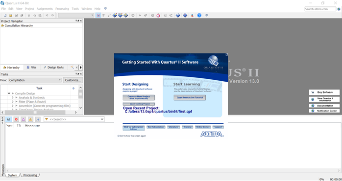
It might be a bit different as I have already created one project before recording this. We can go ahead and click on “Create A New Project”. A wizard will appear and we can just step through this.
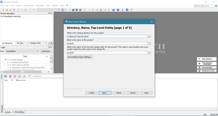
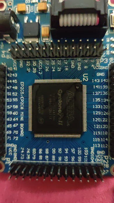
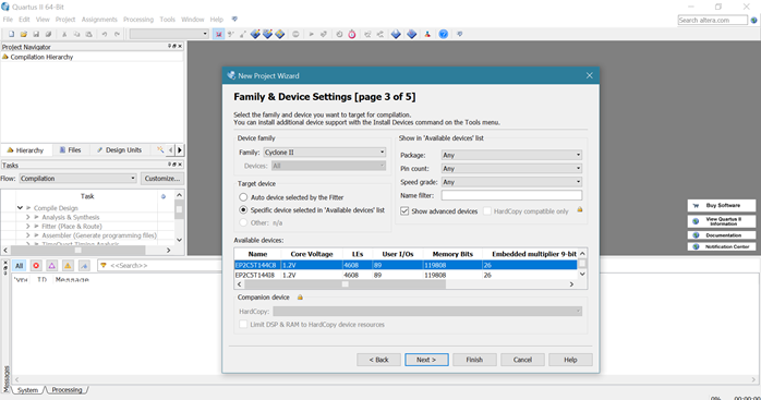
We don’t need to add any files, so you can skip page 2 of 5. In step 3 of 5 we need to choose our board. If you look carefully, you can see the chip number written on your board, mine is the EP2C5T144C8N.
We can skip through page 4 and 5 and click on “Finish” to create our new project. Now we can go to “file” -> ”New” to create a new file.
Verilog
I am going to use Verilog to write the code, but you can choose another method if you are comfortable. I wrote the following code to change the LED depending on the state of the push button. Make sure to name the module the same as the file name.
module first(led1,led2,led3,pb);
output led1;
output led2;
output led3;
input pb;

reg led1,led2,led3;
wire pb;
always @(pb)
begin
led1=pb;
led2=~pb;
led3=pb;
end
endmodule
Pin Assignments
You can now go ahead and compile the project. (Note that it takes quite a while to compile) The next step is to go to “assignments” -> “pin planner”
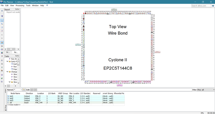
You would have to enter the location of the pins, the LEDs are connected to pins 3,7,9 which the push button is connected to pin 144. After doing this you can compile your project again and we are ready to program. Go to “Tools” -> ”Programmer” and now we need to set up our USB blaster. For this you would need to install the drivers first. I was able to do this with the help of this Blog
Installing Drivers
- First of all, plug the USB-Blaster into your computer
- Now open the Device & Printers "Control Panel - Devices & Printers"
- Under Unspecified, USB Blaster ought to be recorded. Right mouse click on this and afterward select Properties
- Select the Hardware tab & then select properties
- A new window will pop up with the general tab previously chose
- Now select change settings
- Again a new window will be pop up with the general tab already selected. Select Update.
- Now select Browse my PC-laptop for driver software.
- Discover /Quartus/drivers/
- "Remember: Your Altera file is situated at the location you chose when you previously installed Quartus. The location recorded in this document is the default location".
- "Remember: Stop at the driver's folder so that don't go deeper by opening a folder inside the driver's folder"
- Select OK. ensure the correct way was chosen at that point select Next.
- On the off chance that the Windows security window pops up Check the Always trust software from the "Altera Corporation" box & select Install.
And now we can go back to Quartus select USB blaster as the hardware and JTAG as the mode.
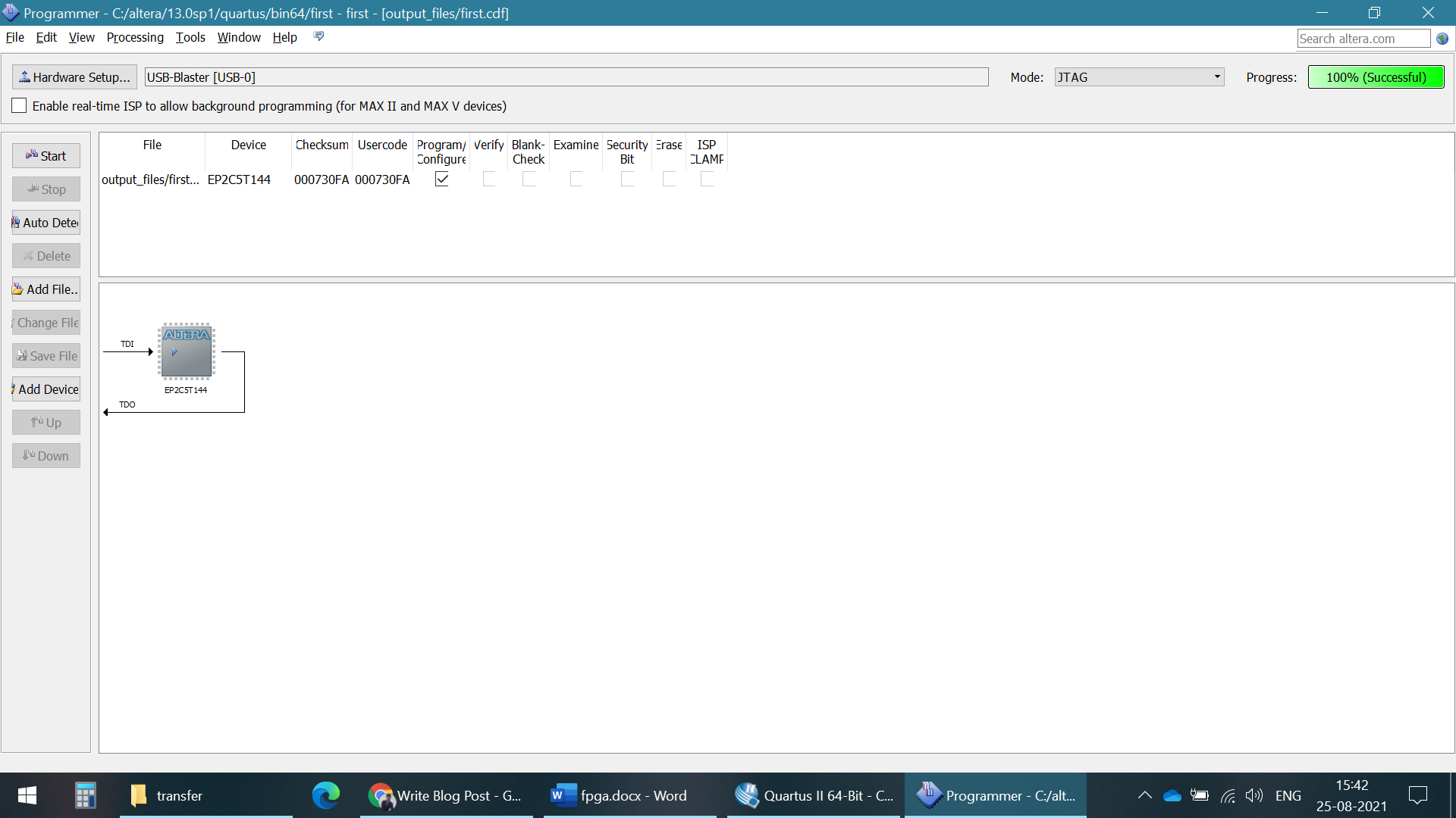
Now go ahead and plug the USB blaster into your board, in the JTAG header and then power up your board with the power supply. Only after powering the board should, you go head and click on start. This should only take a few seconds and if everything worked out, we should be seeing the output on the board.
Output
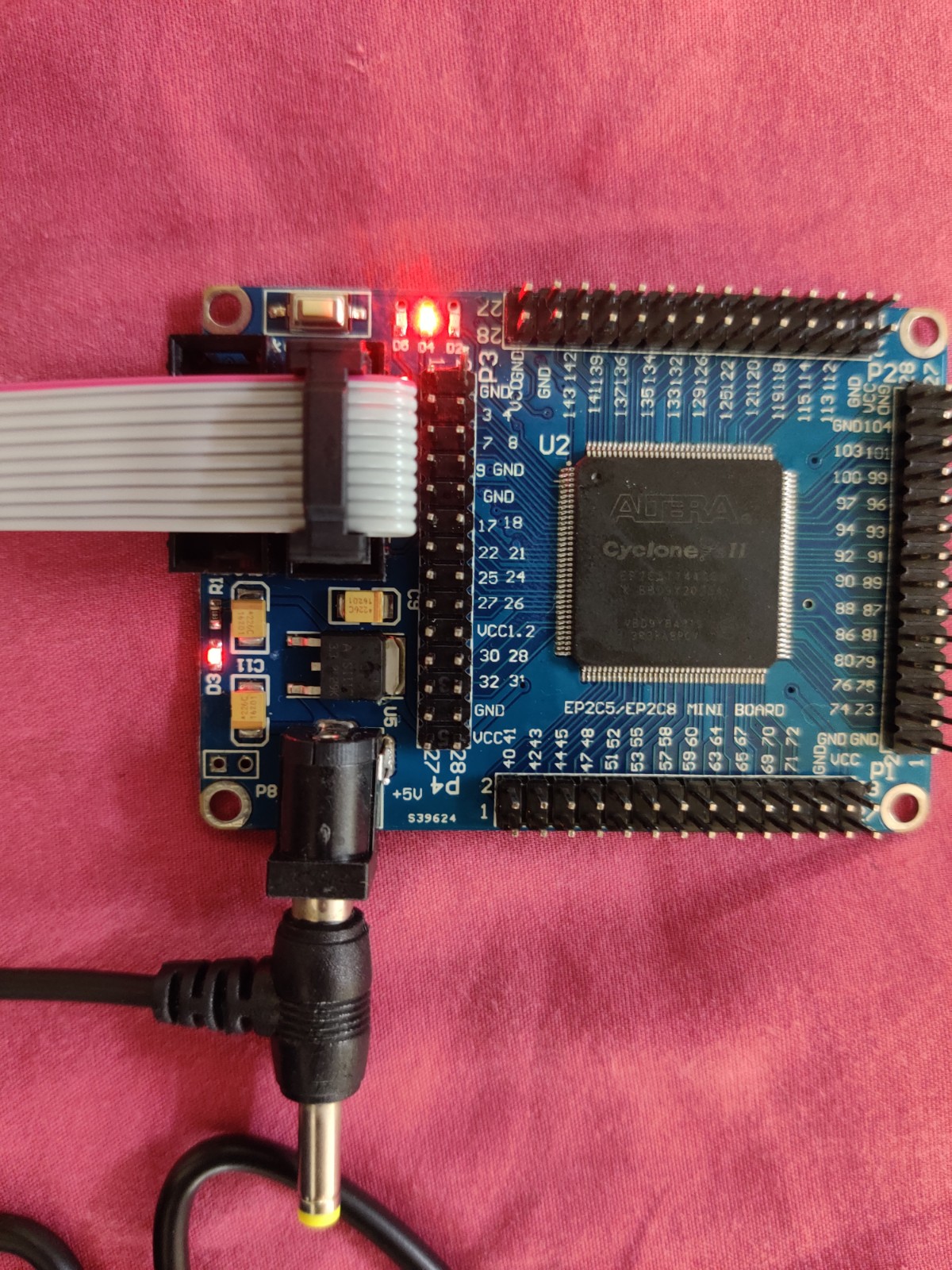
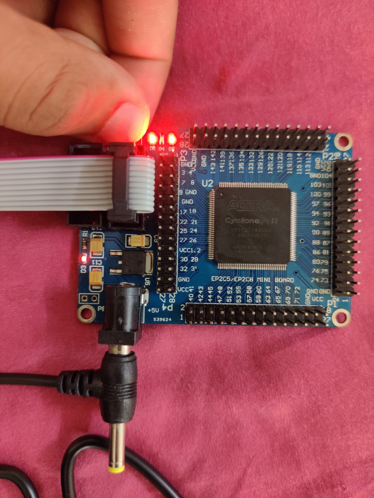
Something you will notice is the push button is very sensitive, it is more like a capacitive button than a push button. This is a known issue with the board. If you had any issue with the process then you can check out this YouTube video where the whole process is explained in great detail.


